The DigiLite DATV project has taken me on an interesting (and kinda expensive) tangent in the last few days.
About 2-3 years ago, after years of doing small Micros and PIC processors, I decided to try out the AVR and the open source WinAVR GCC tool chain for the AVR's. I never did get into Arduinos except for hardware-- I bought a few Sanguino boards which are an ATMEGA 644P version. I got shipped 644's instead of 644P's and it wasn't worth shipping back (my order was correct, the shipment wasn't).. so I used those.
I decided that for the DigiLite DATV project to make my own programming board for the "Ultram Tech" PLL board rather than using the BATC Closed source or F1ACN "demo PIC basic" solution. Initially, I didn't want to do the software work required to use WinAVR (see previous posts when I was working on the HF amplifier-- which I will get back to someday!), so I decided to see how "beneath me" the Arduino IDE actually is/was.
I'm actually fairly impressed by it because it does actually hide the GCC tool chain within it so the actual hit to the performance and RAM is minimal. It is really well designed. In the meantime I decided to order off a Chinese clone of a Arduino 2009 and a LCD shield to go with it. It cost $29 shipped for both. It will be the "GUI" for the PLL project. The physical packaging is nice.. it'll be nice and really that inexpensive PLL with the inexpensive control could also make a really nice "poor man's microwave signal generator". The commercial Arduino 2009 version has a FTDI serial chip on it so ideally my version will have both a 2x16 LCD display and also USB (CDC serial emulation) control over the PLL. I'm getting more functionality out of this unit for less work and $ than the two PIC based solutions.
I think I am going to post on Amateur Radio.com a "Zen of Arduino for Ham Radio" describing the potential uses of these little devices and a small quick tutorial (maybe here if it gets lengthy or too technical). Anyway.. all is well with that project.. It took me about 20 minutes to build up a Sanguino and a HD44780 display and write 80% of the GUI for the PLL. This was before I got the e-bay modules (which are quite nice). To port off to the real Arduino (ok clone) took literally 10 seconds.
I'd have the whole thing done now.. but I need to figure out the control words for the PLL chip... this will be easier when I actually receive the PLL.
I can see the reasoning for "Arduino" even though those are slow, 8-bit processors that are a bit pricey for what they are... but for someone who wants not to delve into programming these are ideal.
Anyway.. I also decided that I should use these to teach the older boys how to start programming rather than starting them off on Linux or MS Visual Studio. So I got the "wild hare" up to dig out another old project--
About three years ago I bought a WizNet812MJ (W5100) module for about $35 with shipping (which was expensive IMHO) to do the DVB-S project on a FPGA. The intent was to use Ethernet at the max 20 Mbps SPI rate the W5100 was more or less capable of. I did get it to go with a small micro, but at the time the code to do the stack was substantial and I ran out of time. In the closet that module went.
I decided, hey, the Arduino Ethernet Shield is basically the W5100..the arduino has a nice library for it.. no work, right? So I made a breakout for the breakout, and put a L78L33ACZ 3.3V regulator on it and wired it into a breadboard. What I didn't realize is that on the Sanguino board the SPI is currently "broken" on Arduino >-019 .. it's fixable but it's not a simple fix.
I almost had it. (It has to do with the Arduino code not knowing the different pinouts of the SPI UART on the ATMega644)..
This is only a minor ARRGH.. though.. I was on my way to find out the issue with the module.. It is, by the way 3.3V but 5V tolerant for the inputs. One thing that has to be done is resetting the chip. I did this by tying into the RESET on the Sanguino. I didn't yet (I'm getting some from...yes..e-bay china) have the little push button reset buttons. So I have been resetting with a jumper wire.
Well.. guess what I did when I almost had the SPI issue resolved on the Sanguino/ATMega644/Wiznet? I bumped the unregulated voltage when resetting it. The Wiznet W5100 is 5V tolerant.. but it's not 8V tolerant! :O( The LCD was fine and the ATMega was fine.. no it couldn't have been something I had multiples of that is easy to get.
So it happens to all of us I suppose. The bad thing here is that it costs about $25/module now with shipping (I did buy two more because I do have a couple of future projects and I want to teach the kids by making a little sensor driven Internet device-- weather station maybe?) and I also decided to buy an actual shield from.. yup... China. I wondered why the lines on the Arduino shield are buffered on a 5V tolerant chip. I now know. So in a millisecond it cost me about $75. OK the $25 for the shield was coming anyway probably.. but $50 for two more modules.. not so much.
Lesson: don't do something that stupid.. or if you do put the chip reset on a GPIO line!
The good news (as it is) is I fired up the X-Tronic hot air gun and got the chip off without totally destroying the board. (It looks good and I didn't drop off anything from the bottom!) So if a place that charges reasonable shipping (Saelig is out, for example) and doesn't require minimum order of 5 of them (like WizNet direct or Jameco).. I can fix the module. SparkFun carries them but are out of stock. So if a SparkFun guy sees this I'd like the $6 solution to the $4 problem too to fix the module I have. !
Like ham radio.. electronics is an expensive hobby. But I do love it and I guess since it became my life and living I am blessed.
But boy do I feel downright dumb tonight.
Saturday, November 12, 2011
Saturday, November 5, 2011
DigiLite update...and SOAPBOX
I did go off and order about $150 total worth of parts for the DigiLite.. I'd guess to get to the "modulator stage" of a DATV DVB-S transmitter that one would need about $275-300 if buying all new.


I also ordered the $55 Ultram Tech (from Israel..e-bay) ADF4360-6 based PLL oscillator board. I am going to write my own control that will use a $29 Arduino 2009 board and a 2x16 HD44780 based board with buttons from e-bay (China) rather than running the "5-button" PIC board hack-up the BATC is running. I need to be able to set my own frequencies, so I need source! I have most of the code done already (Arduino is sooo easy..) but I need to figure out some of the settings that the Analog Devices Integer-N PLL / OSC uses.. like "current setting" and "antibacklash". I don't have the Arduino yet.. but I converted some of the Sanguino's that you'll see in earlier posts to actually be Arduino based instead of hacked with WinAVR as I had been using them.
And Yes.. If I do this, it would be a "bang up" poor mans signal generator for 1200-1400 MHz. Code will be open source... Note also that there is a French Ham doing a version and there appears there may also be a board when the BATC CQ-TV 235 comes out in October 2011.. okay.. we are past that.. now.. so "soon."
I ordered $80 of parts from Mouser for the Chip Tantalums (expensive!** only one is really needed for the DSPic33) Bourns Surface mount trimmer pots.. weird SMT 3.3V regulator***, a couple of PICs, and adjustable regulators for the biasing of the IQ circut.. and other bits).. oh and the $27 FTDI module. By **expensive-- I'd eliminate the stinking chip tants-- which I hate-- if the board was re-laid out and replace with common leaded electrolytics.. I'd use standard leaded pots, ***a leaded 3.3v 78L33 type regulator.. those little things would make the board an inch bigger in one dimension but probably cut the parts cost by $15.) I'd also consider the four port FTDI module FT4432 instead of the FT2232 and use one of the extra ports for SPI programming of the Ultram Tech PLL Oscillator and .. maybe an extra RS-232 port with a line driver on the board? Actually, why not put the PLL chip on the board as well and not have to buy the synth from Israel? (No offense here to Ultram Tech.. good service so far)
All parts can be had from Mouser which is the cheapest overall source other than the Analog Devices modulator chip.. the AD8346ARUZ.. that is a Digi-Key or if you must Newark part.
I programmed my own DSPic and saved the BATC pre-programmed one for a second board. I was going to also order another board from the UK and build it up for 70cm. I can't do that. I do NOT believe it is legal to do so in the US. Many including N1ND who is the frequency rules guy at the ARRL disagree with me. I'll briefly mention why I do not think that DVB-S/C/T or even ATSC is legal on the ATV frequencies on 70cm at the end of this post. I might build a second 1255 MHz unit and loan to other local hams so we could do a two-way.. or maybe I'll eventually build up a 33cm unit.
Anyway.. interestingly enough.. the DIP adapter for the PICKit3 I bought to program DIP based PICs wouldn't work the DSPic33... but a breadboard did! If there is interest I'll write up how to make the programming on the breadboard with the PICkit3. Basically hook up the power to the right places and the ICSP lines and power from the PICKit3 and it works! The lesson here: the bread board is the UNIVERSAL dip adapter.. don't waste the money of the ZIF adapter board unless you are programming a lot of parts!
Anyway.. I don't want to ramble to much, so lets cut to the chase. I don't have the Oscillator module yet, so
I fired the unit up with no LO drive and no MMIC pre-driver installed...
It works... At least up to the modulator out from the DSPic33.. Here is a short video of a "government cheese" NTSC SD-box receiving PBS on the Hauppage PVR-150 with WinTV-6 and then streaming it out with the BATC's software to the PIC which at least thinks it's modulating the signal to QPSK (and would if I had a LO and properly adjusted the I/Q offset/drive). So it's really close:
So yeah.. it works like greased snot. It's slick.. and impressive. There are a bag of tricks to make this happen like the MPEG-2 Conexant chip on the PVR-150 configured (in that case, for 3000 MSym/s and 1/2 FEC for 3 MHz wide signal) for a CBR MPEG-2 NTSC D1 video rate of 2222 and MP2 audio rate of 128K which is really quite sufficient for ham use.. actually.. I'd like to experiment with narrower signals!
At 2222/128 the null packets are very small and most times there is negligible PCR lag.. occasionally though the start-up seems to throw off the DSPic33 at this rate and a restart is necessary for a non negative PCR lag. at 2112/128 this seems never to happen but null packets are about 4.5%.. so somewhere in the middle of the two is probably perfect if you want to run 3 MHz wide D1 Video with decent, but not-quite music quality stereo audio! That's at least 1/2 the bandwidth of analog ATV.
<SOAPBOX>
Meaning this should be a shoe-in for the 70cm band! Much better than 2x the quality and 1/2 the bandwidth! Super lets start using it? Not in my opinion. Part 97 defines image on Frequency and/or Phase Modulated signals as designator F2F or G2F only. Commercial definition from researching license grants to commercial parties show that ATSC is 5M38C7W (or in ham speak C7W) and DVB-S as G7W. No exceptions.. I did not find ATSC defined as C2F or DVB-S defined as G2F anywhere! These designators are explicitally defined in Part 97 as "multiplexed data". "7" and "W" are excluded from Image! So even though there is a clause that states that undefined or digital modes that are substantially the same as the analog equivalent in bandwidth for phone and image are legal.. Legally DVB-S/C/T and ATSC isn't IMAGE.. it's DATA. And data is (WRONGLY!) limited in the 1980's rules as 56K baud (symbols per second per carrier) and 100KHz BW .. so even though NTSC video is not legal anymore anywhere else.. ATSC is mandated.. it's illegal in 70cm under current rules but NTSC isn't.
Yeah, would the FCC enforce this or care? Nope. The ARRL doesn't care either apparently. It doesn't change the fact this is what the law says. This is a warning, people. The rest of the world is going digital and as hams we are not. Are rules are a major reason why. They were intentionally set up in the 1980's to make digital modes second class citizens on the ham bands.. or at least new digital modes.
If you disagree with me and run DVB-S/S2 or DVB-C and some have on 70cm... good luck and I wish you well-- I support you.. but I see it as not permissible.. which is really quite unfortunate. It's legal in most other countries that don't have protectionist rules in their regulations.
End of my comments on this... </SOAPBOX>
Saturday, October 15, 2011
One time rant, get it off of my chest.. then the DigiLite from BATC
Well, now that you can tell that I only am posting short messages once every three months or so, that life has gotten in the way of my other plans... including ham radio.
I've not been on the air since June or so, and had severe house and antenna damage in early July that-- although the monetary loss was minimal, took a lot of my SUMMER free time to fix. I would often operate from the W0CXX club station at work, but they are re-roofing the building, and there are no usable antennas there either for quite some time. So ham radio has been on hold.
I'm probably back to operational on 40m (at least with a low dipole), pretty sure I'm operational on 20-15-10m. My previously poor 75/80m tower feed can be fixed.. but with the 'spots being what they are lately I'm not in a hurry with that.
I want to complete my 12m/17m Moxon/Yagi combo that I've been building out of an old 10m Cushcraft beam. (When I prove that it works I'll post a 'blog entry on it here with an overview at Amateur Radio.com.) I have a 6m 5 element beam ready to put on a roof tower on the opposite side of the detached garage from where I have the tower. It will be a little lower in elevation but should be fine. This has been in the works since spring. I was also going to put up two verticals phased on 40m (and eventually load it for 80m) but I don't see that happening in 2011. Sigh.. for a while there I was really productive with the hobbies. I lost my wire 1/2 square for 40m when a tree fell through it, so it would have been nice to get the phased ones up. Maybe next year. If I don't move and put up everything for auction. That's a different story though not related to the 'blog. But it's sad.. I'm getting upset that I never have time for anything fun anymore. I'll mention this once and try not to use the excuse I'm too busy anymore but it has been the truth.
The TS-590S I bought at Dayton has had ZERO transmit time on it. And maybe a couple hours of RX. BOGUS AND SAD!
I also started to gain some weight after hitting "bottom" with the gastric bypass. It became obvious that I'd need to start working out to go from a "stick" (literally, people were telling me that I was looking bad) to at least gaining some inevitable weight back as muscle. Okay, they *tell* you that 30-minutes of exercise a day is enough.. but it's not... really 4-5 times a week for about 1.5 hours at a time is what I found I need to benefit from it.
But that's, what?, 8-10 hours a week less to do building and operating. But it sure beats going back up to 350 lbs, .... that is for sure.
I even missed the Iowa QSO Party today because I couldn't get home early enough on Friday not to be exhausted with the 9AM start and everyone else in the family had other plans. Only in Iowa would someone think that running a contest from 9AM to 6PM on a Saturday was a good idea. Hell, it would have been nice to have some after dark 40m/75m contacts, right? I work 8AM-7PM during the week. It's not fun to do that on Saturday. If it would have been 9AM to 9AM or noon to midnight or something logical I would have done it. But by the time I got home, and then got to bed at 3 AM I couldn't do the 9AM-6PM thing.. oh well. I suppose the 3AM thing was my fault but as it is it was for a good cause.. I started on it well after 10 PM but I actually had the enthusiasm to do so for the first time in months.. maybe ham radio isn't over for me after all.
So maybe someone who has their crap together much better than I do can tell me how you can be a productive working age adult ham operator and work full time+, have four kids, a wife, and have to work out? I don't want to quit but I starting to think I have to. I now understand why ham radio is becoming a "retiree's" hobby.
Anyway, why was I up to 3 AM? I received a care package via "Royal Mail" on Friday.. and it's something that was designed almost the same way (actually more clever in many respects) that I had been thinking of doing for close to 10 years.
Anyway.. one comment of pride: I haven't yet ordered parts for this board. About a year ago I started to buy parts kits from (mainly China and Thailand but) all over and stocked up modern useful parts for a fairly low cost. Needless to say I have the board 3/4 done from my parts kits. I did identify an issue where I need to stock chip tantalum capacitors or chip electrolytic as I have had more than one case of not having them when I needed them. Okay.. I cheated slightly in that I paralleled a couple of 0805 capacitors to make an equivalent of the called for 1206 value.. and I used 0805s for most of the capacitors (which fit) since it's easy to get good quality kits of 0805's from Sure in China but no one has or normally uses 1206/1210's in industry so you won't see cheap kits on e-bay. I think I was lucky to find a US source for a 1210 chip resistor kit (which ultimately was from China).
I've not been on the air since June or so, and had severe house and antenna damage in early July that-- although the monetary loss was minimal, took a lot of my SUMMER free time to fix. I would often operate from the W0CXX club station at work, but they are re-roofing the building, and there are no usable antennas there either for quite some time. So ham radio has been on hold.
I'm probably back to operational on 40m (at least with a low dipole), pretty sure I'm operational on 20-15-10m. My previously poor 75/80m tower feed can be fixed.. but with the 'spots being what they are lately I'm not in a hurry with that.
I want to complete my 12m/17m Moxon/Yagi combo that I've been building out of an old 10m Cushcraft beam. (When I prove that it works I'll post a 'blog entry on it here with an overview at Amateur Radio.com.) I have a 6m 5 element beam ready to put on a roof tower on the opposite side of the detached garage from where I have the tower. It will be a little lower in elevation but should be fine. This has been in the works since spring. I was also going to put up two verticals phased on 40m (and eventually load it for 80m) but I don't see that happening in 2011. Sigh.. for a while there I was really productive with the hobbies. I lost my wire 1/2 square for 40m when a tree fell through it, so it would have been nice to get the phased ones up. Maybe next year. If I don't move and put up everything for auction. That's a different story though not related to the 'blog. But it's sad.. I'm getting upset that I never have time for anything fun anymore. I'll mention this once and try not to use the excuse I'm too busy anymore but it has been the truth.
The TS-590S I bought at Dayton has had ZERO transmit time on it. And maybe a couple hours of RX. BOGUS AND SAD!
I also started to gain some weight after hitting "bottom" with the gastric bypass. It became obvious that I'd need to start working out to go from a "stick" (literally, people were telling me that I was looking bad) to at least gaining some inevitable weight back as muscle. Okay, they *tell* you that 30-minutes of exercise a day is enough.. but it's not... really 4-5 times a week for about 1.5 hours at a time is what I found I need to benefit from it.
 |
| Rockwell Collins Rec Center Zagrata 5K 9/2011 |
But that's, what?, 8-10 hours a week less to do building and operating. But it sure beats going back up to 350 lbs, .... that is for sure.
I even missed the Iowa QSO Party today because I couldn't get home early enough on Friday not to be exhausted with the 9AM start and everyone else in the family had other plans. Only in Iowa would someone think that running a contest from 9AM to 6PM on a Saturday was a good idea. Hell, it would have been nice to have some after dark 40m/75m contacts, right? I work 8AM-7PM during the week. It's not fun to do that on Saturday. If it would have been 9AM to 9AM or noon to midnight or something logical I would have done it. But by the time I got home, and then got to bed at 3 AM I couldn't do the 9AM-6PM thing.. oh well. I suppose the 3AM thing was my fault but as it is it was for a good cause.. I started on it well after 10 PM but I actually had the enthusiasm to do so for the first time in months.. maybe ham radio isn't over for me after all.
So maybe someone who has their crap together much better than I do can tell me how you can be a productive working age adult ham operator and work full time+, have four kids, a wife, and have to work out? I don't want to quit but I starting to think I have to. I now understand why ham radio is becoming a "retiree's" hobby.
Anyway, why was I up to 3 AM? I received a care package via "Royal Mail" on Friday.. and it's something that was designed almost the same way (actually more clever in many respects) that I had been thinking of doing for close to 10 years.
 |
| British Amateur Television Club "DigiLite" DVB-S serializer and modulator, top side 3/4 done |
 |
| Bottom side, probably more than 3/4 done |
Chip resistors are typically less than 1 cent bought that way. Newark wants upwards of 15 cents/ea for one. It makes sense to stock up on chip components for the coming apocalypse -- it's typically cheaper to do so than to order specifically for one project!
Chip caps, too.. maybe slightly over 1 cent. The 0805 0.1 uF caps I bought a "lifetime" roll of 1000 of them for $20 delivered from China.. they are name brand and are good quality, too. The "Sure" caps are of OK quality but at low RF levels and low DC levels they are perfectly fine.
The DigiLite is based on the "Poor Man's DATV" by F4DAY. The project has been updated for modern computers by using a 2 channel FTDI USB serial port chip (which is the "why didn't I think of it?" part of the design) and a closed-source (unfortunately) DSPic33 and Windows PC software to capture data from a "e-bay special" several year old Hauppage PVR-150, 250, 350 (and probably PVR-USB2) analog capture card. Which are cheap now (about $30 for US NTSC) on e-bay since they only have analog tuners, and many were pulls from OEM PC equipment. What is special about them for this project is an Conexant MPEG-2 encoder hardware chip. Newer computers will soon be able to do MPEG-2 and H.264/AVC MPEG-4 in their CPU hardware, so these older chips for now are the only cheap way of easily and quickly doing digital video for this system. Actually.. I wish there were hardware H.264 encoders out there for a reasonable amount.. but likely there will not be except for embedded stuff because the PC's will handle it in real time without the ASICs.
The modulation used is DVB-S, which is the older digital standard used by most of the world for satellite transmissions. I've been playing with LEGAL Free-To-Air satellite for many years. The majority of what is left unencrypted on C-band and Ku-band FSS satellite is receivable on an inexpensive (from $30 used DVB-S to $130 new DVB-S2 high definition PVR type units) set type box and/or PC receiver card. This same receiver can take in 950-2150 MHz signals as an IF (with a converter and/or a LNA in front of the IF) in Amateur use.
Oh, and supposedly the newer FET based Mitsubishi power modules seem to be much more linear than the older Mxxxxx series bipolar modules.. so generating a few watts of linear PSK seems to be quite doable for reasonable cost at 70cm (but is it legal in the US? Our OUTDATED data rules on that band seem to say no even though bandwidth can be reduced by a factor or 6-8 for more reliable digital signals!), 902-928 MHz, 1240-1300 MHz and probably even beyond.
So this is the start of an interesting project for me that I've wanted to do forever. Hopefully it will turn out well and can be revolutionary.
The bad thing here.. is going back to the rant.. the other project from last year will have to stay in it's current state a little longer.
The BATC's solution of using an inexpensive PIC and the FTDI serial interface is a maybe slightly kludgy but awfully clever solution of inexpensively and simply pumping data to the QPSK modulator chip. Coming up with an exact kludge like that kept me from this project for 8+ years. The only disadvantage to it is that they can only do Symbol Rates (SR) up to about 6250Ksym/s.. but for ham use at this time.. that is more than enough! It's an awesome start!
The modulation used is DVB-S, which is the older digital standard used by most of the world for satellite transmissions. I've been playing with LEGAL Free-To-Air satellite for many years. The majority of what is left unencrypted on C-band and Ku-band FSS satellite is receivable on an inexpensive (from $30 used DVB-S to $130 new DVB-S2 high definition PVR type units) set type box and/or PC receiver card. This same receiver can take in 950-2150 MHz signals as an IF (with a converter and/or a LNA in front of the IF) in Amateur use.
The disadvantages to DVB-S for ham radio is that it is QPSK with Convolutional Encoding and Reed-Solomon FEC.. Meaning that it's about 3 dB "weaker" than the more "modern" BCH/LPDC codes used in DVB-S2 and that it's QPSK -- optimized for weak signals, but pretty weak when it comes to handling multipath.
Current Analog NTSC AM TV doesn't handle multipath well either ("ghosting").. so those who already do ATV are using Yagi beams other directional antennas for their front-to-back and front-to-side directivity more so than the secondary benefit of gain. Experiments with DVB-S for terrestrial Amateur TV/Data links show that the same antennas work to fix many of those issues. Hams will likely use beams at these power levels anyway.
One great advantage to DVB-S for ham use-- and overwhelming one in my opinion is that the bandwidth and data rates, even the video and audio coding the the MPEG-2 Transport streams are pretty much completely up to the link user. DVB-T in Europe and ATSC in the US is only setup for 6/8 MHz channels and IMHO there is no reason for hams to use this much bandwidth in 2011 for ATV.
Experiments by the BATC and others show that the digital signal is much more usable and stable than equivalent bandwidth analog ATV and it just gets better with reduced bit rates.
They seem to do okay with D1-ish video quality (PAL is 625 lines so it's already "more HD" than NTSC) at 1.5 MBPS-2 MBPS with 1/2 FEC for a net of 1.5 - 2.0 MHz of bandwidth. I will argue that eventually even this simple modulator could be redone to do the more modern DVB-S2 standard, with more advanced audio codec (more compression) and H.264/AVC type data. We are not far off of that. I could see with DVB-S2 and H.264 that 1 MHz wide studio SD (D1) could easily be possible and to boot the C/N ratio to decode these signals can almost be 3 dB less, or even more advanced modulation like 8-PSK could be used to further reduce the bandwidth for a 4dB or so hit over Mpeg-2/DVB-S. Is it possible for 500 KHz FS video? Probably but the consumer grade Set-Top-Boxes might not be able to support it. Most can be coaxed to do 2000 Symbol rate or even 1500... I've heard of some doing 1000.
Ho, Hum? ATV? who cares? Well.. see.. it's not really just that, is it? The data on DVB-S is transmitted as as Transport Stream (of 188 byte packets) but there are protocols such as DVB-IP that can do internet over DVB modulation. There are $20 e-bay boards capable of receiving this as a native computer network interface. If we can write a data driver to go the other way... half and full duplex multi megabaud links could be done for the price of a Digilite and a TwinHan or SkyStar (or even cheaper like old Broadlogic) DVB-S cards and the supporting RF amplifiers and preamps. That would have to be a boon for things like emergency communications... and maybe even getting a packet radio network up again.
Oh, and supposedly the newer FET based Mitsubishi power modules seem to be much more linear than the older Mxxxxx series bipolar modules.. so generating a few watts of linear PSK seems to be quite doable for reasonable cost at 70cm (but is it legal in the US? Our OUTDATED data rules on that band seem to say no even though bandwidth can be reduced by a factor or 6-8 for more reliable digital signals!), 902-928 MHz, 1240-1300 MHz and probably even beyond.
So this is the start of an interesting project for me that I've wanted to do forever. Hopefully it will turn out well and can be revolutionary.
The bad thing here.. is going back to the rant.. the other project from last year will have to stay in it's current state a little longer.
Thursday, August 25, 2011
Summer Blues
Just a quick post to verify that this blog is working. I can't seem to comment on a comment on another page.
I am going to get back to posting at least once a month here and/or at Amateur Radio.com
Summers are pretty tight for me anyway (I do have a XYL and four young kids remember).. but I had storm damage this summer that also made me go QRT. I'm starting to catch up. I"m about at "the end of June" now.
I will be back and the projects that seemingly got abandoned in May will start back up. Until then... 73
Sunday, May 29, 2011
The value of knowing what you are doing...
...and double checking everything even when you might not otherwise think it is necessary...
Well.. I spent a small fortune on ham radio in the last two months or so. One purchase is a new TS-590S and the other... well...
I bought a used TL-922A that was in very good cosmetic shape about three weeks ago. Didn't have time to fire it up until today. It has new RF Parts 3-500ZG tubes, AG6K suppressors... and well it had a 160m "improvement" mod done to it. I paid good money for it. Enough that I'm almost embarrassed to say, depending on how this all turns out. Cosmetically 9/10.. Good power out for the 3/4 hour or so.
Now I hope it still has a functional HV supply. I am wondering if I have another SB-200 that I finally got everything shaken out of right before buying the TL-922. (Took 9 years.. but then again, it was a cheap amp to start off with...) It was putting out 1000-1200W on all bands I tried (as it is supposed to) with about 85W of drive.... 80m/75m, 40m, 20m... 15m *POP*
eek...crapola.. that was a lot of $$ that went up in smoke...
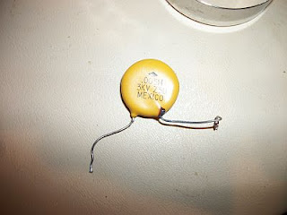
Here is the culprit:


Anyway.. it's starting to be that sort of weekend. The TS-590S seems pretty impressive and I am looking forward to running it with this amp.. but maybe I'll be out over $1K (I said it) and will have to use the ugly SB-200 with it instead.
Sigh..
From a physical check of the unit, it all else seems good (no smoked parts).. so once I can get over to the local Grainger store to get this oddball fuse, I am *hoping* I can fire it back up.

Anyone else want to comment on the extra 0.005 uF... should I start digging for a doorknob to add to the amp, or was it a stupid "improvement"?
Needless to say.. the moral of this story is do not parallel or replace a doorknob with a disc! Do not put a 3 kV disc in a 3.1 KV DC circuit with over 100V of AC injected on it. sigh...
Well.. I spent a small fortune on ham radio in the last two months or so. One purchase is a new TS-590S and the other... well...
I bought a used TL-922A that was in very good cosmetic shape about three weeks ago. Didn't have time to fire it up until today. It has new RF Parts 3-500ZG tubes, AG6K suppressors... and well it had a 160m "improvement" mod done to it. I paid good money for it. Enough that I'm almost embarrassed to say, depending on how this all turns out. Cosmetically 9/10.. Good power out for the 3/4 hour or so.
Now I hope it still has a functional HV supply. I am wondering if I have another SB-200 that I finally got everything shaken out of right before buying the TL-922. (Took 9 years.. but then again, it was a cheap amp to start off with...) It was putting out 1000-1200W on all bands I tried (as it is supposed to) with about 85W of drive.... 80m/75m, 40m, 20m... 15m *POP*
eek...crapola.. that was a lot of $$ that went up in smoke...
Here is the culprit:


Okay.. the guy doing the mod did nice clean work.. HOWEVER.. one cannot bypass (the glitch resistor too! I hope the HV is ok...!!!) the plate supply, which is 3.1 KV (SSB) on the TL-922 with a 0.005 uF 3 KV disc!!! (The other end was attached to the interlock mounting screw for ground with longer leads than I would have liked as well.) I suppose if that is a major improvement on 160m and 80m that I can add about 5000 pF with another 7 KV+ DOORKNOB cap.. but this addition made the amp pop and go boom within about 45 minutes of when I first turned it on.
Unfortunately that cap is now a 55 ohm resistor and it did take out one of the two "Bussman" FNM-15 time delay fuses. I'm keeping my fingers crossed that the supply can take it. The interlock is there also, but it's still a frightening proposition when something like this happens!
Of other interest, and I am going to e-mail Rich Measures... it appears that the resistors in the suppressor kit (which are bypassed with the nichrome wire and getting a little discolored. I don't know if that is because of the cap venting out (it is possible) or there is something else wrong.

See the suppressors look like they are installed correctly (according to what I've read on the web), however the ones that are bypassed with the nichrome coils seem a little discolored at the ends. I am gong to e-mail the designer of these suppressors and see what he has to say about that.
Anyway.. it's starting to be that sort of weekend. The TS-590S seems pretty impressive and I am looking forward to running it with this amp.. but maybe I'll be out over $1K (I said it) and will have to use the ugly SB-200 with it instead.
Sigh..
From a physical check of the unit, it all else seems good (no smoked parts).. so once I can get over to the local Grainger store to get this oddball fuse, I am *hoping* I can fire it back up.

Anyone else want to comment on the extra 0.005 uF... should I start digging for a doorknob to add to the amp, or was it a stupid "improvement"?
Needless to say.. the moral of this story is do not parallel or replace a doorknob with a disc! Do not put a 3 kV disc in a 3.1 KV DC circuit with over 100V of AC injected on it. sigh...
Thursday, April 14, 2011
Other 'blog and Spring "slowdown" -- Shameless begging
Sorry I've been so quiet lately. I've had an over month long stint of 50+ hour weeks at work, a lot of stuff to do with the kids, and I also got invited to post at a more general interest Amateur Radio 'blog. It is my intent to still post here-- with more details on my projects-- but I will do more general interest and synopsis type stuff at the other site. Weather in IA is only good about 5 months a year, and I have to do outside stuff starting now, or stuff will fall apart around me-- more than it already is!
See AmateurRadio.com for some of my other posts. I may cross post some of the stuff, but since the interfaces between the two sites are a lot different, that may be too time consuming. (The other site's "wordpress" interface stinks, IMHO.. but it is what it is!) I invite anyone interested in my drivel to look at the other 'blog as much of it will be more interesting than my (highly biased!) thoughts on the hobby.
I have a lot of stuff in the works, if and when I get it done (if and when I ever have free time again to work on it).. there will be flurry of postings at both sites, and hopfully completed projects will go to the website. It takes a long time to properly document the projects, but there are inherent advantages to doing so.. so I intend on 'blogging the results.
Projects still in the works:
The HF amplifier project, and SDR-Cube to "general purpose HF rig". This is the long term one. The AN-762 Amplifer is done minus the finals being mounted. The K5OOR amp filter is done, but I still want to bring it into work and tweak the filters on a VNA. Then I need to interface it to the AVR and write a little code to idiot proof the operation of the Amp.
Antennas: 18 MHz/24 MHz WARC beam made from a Cushcraft 10-3 and other surplus antenna tubing I had lying around. This is almost done, but needs to be tuned. It should be a useful writeup when I get it done. It's a "Moxon" (Cebik) Rectangle on 17m and a two element "open sleeve coupled" (coupled resonators is a better name) two element yagi on 12m.
Antennas: 6M beam on the same mast.. a 30m dipole either rotatable on the same mast or as a wire from the roof tower (6M and WARC) to the main tower. Of course the roof tower needs to have a rotor put into it, a thrust bearing mounted and it be bolted to the roof of the garage opposite to the main tower...
Antennas: two element phased array for 40m. I have new tubing from DX engineering for this and was hoping to have posts in the ground by now. I think I'm going to elevate the radials since it's probably already too late to lay them down and have the grass grow around them this spring! :O(.. I can always add a screen under the elevated ones later. On 40m I don't think it's so critical.. 80m and 160m you probably cannot elevate the antenna enough practically to make the elevated radials work worth a darn. I have my own theory on this but can't prove it so I may never mention it.
and.. I have a shed kit to build to get the mower and snowblower out of the garage to try to make up some room that I took away when I put my hamshack room in the detached garage by the antennas.
Operating: Still working on DXCC (only have 41 confirmed out of about 120 countries worked for ARRL, less on eQSL.cc..) I just got envelopes and foreign stamps from William Plum and some IRC's from the post office, so the $6 per country cost to get mail QSLs is starting. Cocaine is a cheaper hobby, methinks.. Also working on WAS. I could use some help with this. If you are in KS, RI. ND, SD, MN, ME, NV, WY and are willing to QSL LoTW or paper I can use you (also eQSL.cc would be highly appreciated too). If you are in LoTW and in DE, UT, MT that's easier than the card checker! All skeds can also be arranged to get/contact a Collins ARC card (quite collectible-- very nice) because I can also contact you as W0CXX. I'm also willing to do this from a vintage Collins radio as well if it's near working hours in the midwest. Contact me via e-mail via my QRZ.com listing e-mail. This offer also goes for *any* DX even if it's something I already have confirmed. I'll do it for any stateside as well... :)
So it'll be a busy spring. I appreciate the followers of this 'blog being patient. Hopefully I'll get it all done and have some good posts upcoming.
73
Saturday, March 19, 2011
Snoopy come home...
Well.. decided to try out the BeagleBoard-XM finally. You know what? Once you realize that a 5V 1A supply isn't going to cut it no matter what the beagleboard.org instructions say and you move up to a 3A (15W) supply.. then you are fine.. Otherwise it's fun watching the device reboot itself endlessly!
Note the Meanwell supply that I use with the Trimble Thunderbolt GPS Disciplined Oscillator. It's rated at 3A at 5V (15W) which is what you want to run with the BB-xM. I hear you can use 2A supplies.. but 3A is guaranteed to run everything. 1A will not work. No matter what you read.
Here is a picture of the BB-xm running the TI (arowboat) image of Android Froyo 2.2 .. It's cool.

The graphics on the flat panel (big) monitor there is a 3D demo that TI put on the image. It ain't too bad.. it does show what the device is capable of. The Android distro though thinks it's on a phone screen so the resolution is a bit limited.
I'm a little disappointed that video tends to crash the thing under the Android native apps. A sure bet is to try to watch a YouTube video.. Ironic isn't it? After about 15 seconds it crashes the system fairly hard.
So even though I'd still like to learn how to write an "Android app" I'm thinking that I may be looking for a different Linux distro for Ham Radio and/or SDR use. (Maybe Angstrom. Ubuntu is reported to be sick with the Beagle-xM unless you do a kernel patch...)
Interestingly enough a certain ARRL Midwest Division Convention probably will have a class on the BeagleBoard XM on August 5th (Friday)... at the Clarion Hotel in CR. look at http://convention2011.cvarc.rf.org for details... We hope to push this as a ham SDR embedded platform-- it has a lot of potential for little financial outlay.
Tomorrow is the ND and OK QSO parties.. I need both confirmed for WAS (and ND on eQSL for eWAS)... so I need to get to bed and work at least five stations from each state this weekend.
I worked OK last weekend but I suspect I'll need to turn a card around to get confirmed from that station. I'm cheap, I try to avoid spending the $0.10 for the envelope, $0.40 for postage and $0.20 for the card or thereabouts. I'll save that for DX. So ND and OK stations.. use LOTW and eQSL.. please?!?
Sunday, March 13, 2011
QTU
I have been really active on the air this weekend.. I decided to try to fill holes in my WAS (and DXCC) paperwork.. I decided 25 years I'd do that. I got the eQSL DX "25" award too.. I figured "why not"?
It's been harder than DXCC on LoTW is (so far)... so "so much" for the "ultra secure" LoTW being the "harder" system. There are times the ARRL really irks me off (tho I support them greatly). LoTW is so obtuse that 25% of the DX stations that WOULD participate on it say "hell with it!" eQSL is "not legitimate" to many. I look at is as a different award, like CQ awards are.
I did work a 3905 Century Club net, a whole bunch of DX and the Wisconsin and Idaho QSO parties this weekend. I hope with 10+ Idaho and 100+ Wisconsin that those will get confirmed in eQSL.cc and LoTW.
It is rare that I do 100+ contacts on a non-field day or DX contest weekend.. but I did. I'll pay for it. The XYL is already mad at me.
"QTU" is the problem though this weekend... Something is hosed on the shack PC (I'm hoping a dead battery on the Real Time Clock on the motherboard) of the old PC. Last night I just thought it was Daylight time and the fact that the HRD logbook (but not DM780 oddly enough) has issues with Daylight time transitions. I probably blew some DX by having the stupid computer changing time on hour boundaries randomly. I'll replace the CMOS battery and hope it fixes...otherwise it'll have to be replaced. I've never seen a computer change time by itself.. but it's doing it every hour now.. I don't quite get it.
I also bought on a whim and took delivery of $213 of telescoping Aluminum ordered from DX Engineering. I'm going to replace my 40m half square (on which I worked South Africa on last night) with a hopefully better performing phased array of two (maybe eventually four) elevated radial verticals on 40m. If it works I'm thinking I'll need to do a 66 foot vertical too with a pulley on it so I can use it for 80m and 160m. I'm starting to like the low bands. In the winter I can do beverages so that should work next fall/winter.
Need to have the ground thaw for a week or two first...
I've not forgotten about the SDR Cube and the AMP projects.. I just wanted to so some spring stuff and operate.. if I never operate what is the point of all of this?
I'm really tired.
TTFN.
Sunday, March 6, 2011
Still ticking
This is a time of year for me that tends to get chaotic.. so the ham projects naturally slow down.
I'm also been too lazy to take pictures in the last few weeks too.
Lets see.. I started building up a PIC32MX795 .. but am short the 8 MHz crystal I will need to bring it up for USB use which.. well I might as well. I did get the boards from Hong Kong to prototype the 0.5mm "PF" center PICs and I've built two up. I actually, for the first time in a long time damaged one of the boards and PIC trying to fix the damaged pin. So one of those two are missing Pin 74.. which for my use I do not think will matter.
The boards I used for PIC32 prototyping are about $2 on e-bay and are by "ETT-Team" in Thailand. They are decent for the price but are a bit heat sensitive. The one I damaged was one I tried to reflow skillet solder.. I think I overheated the board and that plus having a slightly bent pin on the device that I didn't notice from the sample pack had me do a dreaded bent and shorted pin. I should have done better with it but I did it in a hurry.
The second one I just hand soldered down and it's perfect. So.. on those 0.5mm PICs I think I will hand solder. The 0.4mm leads, even though are smaller.. seems to be of a "tougher" material and actually to me are easier to solder. If I finish this and then lay out a board, I'm going to go with the PT 0.4mm package. I had no issues reflow soldering the 0.4mm PT's,,,
I worked the first 9 hours of the ARRL SSB DX contest from the club station at work, under my callsign. I got to use the Alpha 87A and I can see why people pay the bux for those amps. I was just looking for DX for DXCC (and Alaska for WAS) so I was only "hunting and pecking". Still on 20m (for about 1 hour), 40m and 80m I worked 86 contacts and 59 different countries (including AK & HI). Not bad.. was fun too. I wanted to get back on 20m the next day, but our local NWS spotter training was on Saturday and I had to do or I would have lost the credentials. I bet I could have done 25 more countries the next day.
I want to get back and finish the amplifier.. I suppose I ought to.
I also have a BeagleBoard-xm coming still and I'll use that as a distraction on my other projects too. There is interest in using that as a basis for a self-contained (including Latency) SDR within the W0CXX club. We will see if we have time to take that on also.
I also found a deal on a HD Radio to play with..$19.99.. so far, I can see why it's a dead end technology. In Cedar Rapids, only one commercial FM station (KZIA) has HD (hybrid digital, not "high-def" by the way).. and supposedly two AM's do 1450 KMRY and 600 WMT. I got the HD signal to lock on KMRY for about a second and it sound surprisingly good.. but it's not usable. I'm only about 20 mi away from the transmitters too! 600 WMT is very strong here, and I'm wondering if they turned off the HD signal? On FM, KZIA's HD subchannel 2, a classic rock station, is very good. The non-commercial stations, three, are all very good though.. there are additional subchannels that have NPR programming on them.. and in one case the NWS weather radio-- that sounds better than over the FM weather radio.
I was hoping to try DXing digital AM.. I like in the country and have put up beverages in the past, and EWE's Flags, K9AY loops are no issue either. But I doubt if the signal levels I'm feeding the radio with on 600 and 1450 aren't cutting it for HD AM.. neither will a DXed station from a Beverage.
So I'd say when I replace my failing factory head unit in my car I'll spend the extra $15 difference just to get the WX radio off of KCCK...well that and the very good HD2 channel of KZIA.
But when the difference was $100-$200? Who'd ever buy that? It's one of these technologies that could have been very good if it wasn't implemented in such a "half-fast" way.
Anyway.. that's all I've been doing lately for "fun stuff"... When I make progress on any of my open projects, I'll let you know...
Sunday, February 20, 2011
Busy... and all the stuff since last time!
I didn't want anyone to think I've dropped off the face of the earth being more than a week since I posted..
I've not felt overly well.. something is going around Cedar Rapids that everyone I know feels dead tired all the time.. I have it too no doubt.. all I want to do is sleep... even more so than normal! That makes it harder to force yourself to work on projects until midnight when you get home at 8:30 PM from work! :O)
I showed off the SDR-Cube to the Collins ARC, ordered a TFT display from China (touch screen $29 bux delivered) on e-bay and got some PIC32MX's to play with sampled.. I want to port the DSP-Cube GPL'ed software to that platform... that'll take me a while to get the stuff and to hack it together and to then get something running. I sampled and got some PHY's from National Semiconductor (thanks NS and Microchip) and will make the PIC32MX795's I have do Ethernet as well. I'd like to lay out a board with a PIC32MX, a National PHY and magnetics, with the interface to a CODEC and the TFT module... maybe in calendar 2011.. we will see. It takes a lot of time to do this and I'm thinking Kicad instead of Eagle this time.. so I need to learn that as well... In the meantime it will be protoboards and point to point.. but that's fun too...
Being that I am a masochist I also ordered off a BeagleBoard-xm. I think that could be a higher end SDR platform than the DSPic and PIC32MX. My talk at the Collins ARC convinced me to pull the trigger on this.
I fixed up the shack PC on Saturday (yesterday)-- windows update, etc. I worked the Feld-Hell sprint... it was unusually fun.., and also later that night decided to load, dual boot Ubuntu on to the PC, while listening to the AM guys on the Antique Radio QSO Party. I did this all on the old Kenwood because I didn't want to futz with the temperamental Flex-1500 and only run QRP 5W... maybe when the AN-762 is done...
I am a Linux advocate, but for God's sake, people-- will you ever just get a distribution done that works out of the freakin' box? The Ubuntu 10.10 ran off the CD okay but crashed big time when I installed it dual boot with Windows. This has happened for the last three years/attempts (once a year) at installing Ubuntu. What happened this time is that the computer I put it on (the shack PC) is a dual Pentium-D "mini" PC that I added a "small form factor" (it's a SFF machine) Nvidia card to... I wanted dual monitors and no ATI I could find would fit!
Well.. the install set "X" up the Ubuntu boot for the proprietary NVIDIA drivers but never installed them! Huh? What? CANONICAL: NO FRICKIN' EXCUSE! NONE. NADA. Next time: Fedora! You bunch of Commies! (That's another issue I don't like about Ubuntu.. but I won't make this political except for hints of my ideas...)
No "NORMAL" person wants a four hour @#$@#ing debug session after the install. I'm a freak, and I don't want it. Last three times I've had it and it's always been because of my "weird" hardware. You know what? It's not weird and that is an excuse whether you like it or not!! And all three of my computers being weird? Nope it's Ubuntu thats weird.. sorry... It's been video 2/3 times too..
I installed the NVIDIA proprietary driver directly.. it worked fine after that. But that was hours later...Once I finally updated half the CD (over 400 MB!) from my slow satellite internet (why the hell did I get the CD image on the fast connection at work in the first place? You suck Canonical...Sorry no other way to say it!) and then got the thing to finally come up in recovery mode in console mode and typed "startx" and saw the error... uugh...
Got on the net and found how to install the NVIDIA "horrible proprietary" driver manually.. did it, rebooted it and it just worked. Hmm.. how bad is proprietary software? Maybe a lot.. but in this case it made the system usable.. which is more than it was from the Canonical Ubuntu stock install! !!!!
Really.. I don't want to hear that crap that Windows is harder to install than Linux.. Ubuntu is supposed to be the desktop Linux "for everyone" (Commies... sorry I did it again...).. and I'm a software engineer who at one time submitted stuff for the Kernel.. and because of this was able to debug a basic install that I shouldn't have. What? 15 years after the first Linux install I did? NO EXCUSE.. NONE... I got it but it was insane to have to debug the install on such common hardware!
If I want to be serious about running Android on the BeagleBoard-xm I needed to get a decent i386 Linux running again.. so I am there. And I'll be happy to run Linux again.. but it's the last Ubuntu I'll ever do.
I do have an image of Android for the TI ARM based Beagle ready... hopefully Mouser will ship 3/8/11 like they estimate. I figure that board will be a good learning experience for me.. maybe I can get my nine-year old to program that. I have to say that I plan on teaching my children programming the way I learned it... that is from small "embedded" (I did 8080's and Z-80s starting in 1977 and back then that wasn't embedded... but that is the power of current "embedded")...8-bit to 16-bit to 32-bit to doing the BeagleBoard to VisualStudio. If I can teach them that way I'd feel good about doing that so the kids can actually understand low level...
I operated the FeldHell contest this weekend plus some random PSK.. so I finally got on the air again too.. I need to get my CW up so I can do some.. but, my god.. 40 WPM+ on the DX contest.. I'll never get there.. I'm too retarded when it comes to "automatic" responses to learn Morse that way... hopefully I'll get on the weekend of 3/5.. I really want to get those 25 countries I need for DXCC and those 15 states to finish up WAS...
Again, being licensed for 25 years I'm trying to make up for lost time on the radio front.. I'll get there eventually...
I did build up the filter bank on the K5OOR board.. but haven't had time to tweak on a VNA on work yet.. I will post details when I get there... until I do... Sayonara...
Friday, February 11, 2011
This week in W0FMS Amateur Radio
Getting busy... hopefully no one missed me too much. I'm probably the tree falling with this 'blog anyway..
First of all I prepared for the CVARC (local ham club) "show-n-tell" and got totally outclassed by Dave Cripe NM0S... well someday I'll get to his "QRP" greatness.. I think I might have took second place there.. but nice thing about CR is that there was at least two other tables of good projects there.
Lets see.. Had "issues" with the 5W class-A RD15HHF driver amplifier. The issues really were the 0.1 uF "SURE" 0.1 uF "50V" (really 16V) 0805 capacitors. Once I got them to smoke .. and replaced them with surplus Kemet mil 100V leaded (chips inside the package tho) caps... well the amp is as designed.
I think probably more cheap Chinese 0.1 uF's are in my future, though (since I ordered a full roll of 4000 of them off of e-bay this week....!) The solution for that is to parallel a bunch of them. Everywhere in the circuit I had three or more worked/survived.. Two or less...*POOF* (NO MORE POOFTERS!). Weird low pass filters got created on the +12V supply to the FET and then smoke "on the bypass.. fire in the cap" when I got fed up and pushed them. Kemets fixed the situation. More than three cheap Chinese caps seem to about = one good American cap. One American cap $ = 5-6 Chinese. Solution: 4 or more Chinese..
New board (post capacitor fire) looks like this:

New Schematic...

Puts out 7W.. 5W somewhat clean at 700 mA Quiescent (yeah this isn't efficient but could be used at 2-3W *without* low passes and is flat from about 1 MHz to 60 MHz) At 5W about +20 dBm is needed clean it drive it. Gain is 18-19.5 dB across all of HF and into 6 meters.
[C8, C9 were the caps that decided they really rather be LED's.. if you were wondering... they were also the source of my mysterious loss of Drain current with drive and all sorts of other nasty things...]
So that's getting there. I might just do two of these in series for the driver for the AN-762. It'd be a bit of a waste of 24W from the power supply but the "Barack Obama" green police are not after me yet. It's simple and clean. At 100mW out or less it's so clean you wouldn't believe it (2nd harmonic is down like -50 dBc at +20 out).
Also got the X-Tronic "fix and concession goodies" in. What can I say.. hot air unit was less than perfect when I got it. Seller probably knew this. But seller gives out good amounts of freebies to compensate, buyer is okay with that.


First of all I prepared for the CVARC (local ham club) "show-n-tell" and got totally outclassed by Dave Cripe NM0S... well someday I'll get to his "QRP" greatness.. I think I might have took second place there.. but nice thing about CR is that there was at least two other tables of good projects there.
Lets see.. Had "issues" with the 5W class-A RD15HHF driver amplifier. The issues really were the 0.1 uF "SURE" 0.1 uF "50V" (really 16V) 0805 capacitors. Once I got them to smoke .. and replaced them with surplus Kemet mil 100V leaded (chips inside the package tho) caps... well the amp is as designed.
I think probably more cheap Chinese 0.1 uF's are in my future, though (since I ordered a full roll of 4000 of them off of e-bay this week....!) The solution for that is to parallel a bunch of them. Everywhere in the circuit I had three or more worked/survived.. Two or less...*POOF* (NO MORE POOFTERS!). Weird low pass filters got created on the +12V supply to the FET and then smoke "on the bypass.. fire in the cap" when I got fed up and pushed them. Kemets fixed the situation. More than three cheap Chinese caps seem to about = one good American cap. One American cap $ = 5-6 Chinese. Solution: 4 or more Chinese..
New board (post capacitor fire) looks like this:

New Schematic...
Puts out 7W.. 5W somewhat clean at 700 mA Quiescent (yeah this isn't efficient but could be used at 2-3W *without* low passes and is flat from about 1 MHz to 60 MHz) At 5W about +20 dBm is needed clean it drive it. Gain is 18-19.5 dB across all of HF and into 6 meters.
[C8, C9 were the caps that decided they really rather be LED's.. if you were wondering... they were also the source of my mysterious loss of Drain current with drive and all sorts of other nasty things...]
So that's getting there. I might just do two of these in series for the driver for the AN-762. It'd be a bit of a waste of 24W from the power supply but the "Barack Obama" green police are not after me yet. It's simple and clean. At 100mW out or less it's so clean you wouldn't believe it (2nd harmonic is down like -50 dBc at +20 out).
Also got the X-Tronic "fix and concession goodies" in. What can I say.. hot air unit was less than perfect when I got it. Seller probably knew this. But seller gives out good amounts of freebies to compensate, buyer is okay with that.
New standoffs in place in X-Tronic 4000 "Hot air + Soldering". Guess what? They have only a hot air unit now.. I could have saved $50! UGH!
But I did get a good amount of freebies and the soldering iron with that unit is decent. For most the X-Tronic 4000 + soldering iron is recommended.. Freebies follow:

Nozzles.. this time with the correct set of them. Yes the one I was missing prior to this was the "perfect" one for IC SMT rework. But I do have a whole new set. I got a couple of free replacement heaters. I can't say for sure.. but they are "Gordak" (I think from planet "Ork") replacements for .. well Gordak... and ... well.. Aoyue model numbers.. 850A for example is very Aoyue-ish. Not saying the Aoyue and Gordak are the same.. but they might be?
If so the X-tronic is a better deal, no doubt. X-Tronic is "no doubt" made by Gordak.
I got a schematic leaked to me of the X-Tronic 4000 back board. It's completely analog.. no computer controls the heaters.. so it's safer than I thought to leave it plugged in.. but I still wouldn't because all of the DC supplies are always on to the tune of 12-15W AC. Unplug it after cool-down when not in use! The heat gun and iron both use "K" type thermocouples and LM368 Quad Op-Amp comparitor circuits to control the solder heat; the air gun heat and the fan motor on the heat gun. A second loop shorts off the air gun heat TRIAC but keeps the fan on until the secondary loop says otherwise.. factory cal'ed at 55C on my unit.
The display on the front has some sort of "K" thermocouple to deg C multimeter circuit. I should dig on the part number and find the jumper on it that will change it to deg F. $5 says it has one. (Ok.. I'll not bet.. but it probably does.)
Lastly..
I've needed an impedance bridge for "L" at least for awhile. I'm cheap I don't want to spend $100+shipping on the AADE unit. So I won't. Really, I refuse to. I had all of the parts in my junk box, so I was so cheap I didn't even get the PCB board. But it's probably a good thing as my USB sound card (Chinese, of course) for my netbook has R&L channels wired backwards from WB6DHW's board and the original article's Soundblaster Live! card. That took me a few hours to figure out and fix too.
Anyway.. it's good enough that I can wind my Toroids on it and not bother with the HP LCR bridge at work.. but the HP bridge DID calibrate my loads for this bridge! :O)

I'll give WB6DHW credit. The ICL7660D chip for the negative bias off of the USB 5V (regulated to 3.3V and then made -/+ 3.3V for the LM358 Dual Op-amp by the ICL 7660) was rather clever. Especially since I "stock" that part (and ordered more from e-bay since I'm getting "low".) The +/-3.3V is claimed to be safe for the sound card. Since accidentally disconnecting the Rm load puts +2.0V DC on to one of the channels with no ill effects.. I think that putting the ST 78L33 regulator first wasn't a bad idea after all-- instead of having probably +4.5V DC, +2.0V on a screwup is better on the sound card. The circuit overdrives the heck out of the card as it is.. but if you follow the author's instructions that is alleviated pretty well.
The negative voltage generator is needed since the Op-Amp is being used as a one to one High-Z to Low-Z device (a "power follower") and attempting to do the voltage divider for the + input doesn't work well in this configuration. The ICL7660D does though.
The bridge at 4 KHz is good down to about 50 pF.. L seems to be good to about 100 uH or so.. R.. probably several hundred K ish. Not a bad unit.. very accurate too if you pay attention to the proper impedance of what you are measuring and balance the bridge to 10:1 or better for what your are measuring by adjusting Rm.
Verifying level with a scope makes it more accurate as does taking care to balance the bridge out and set the various "tare" points.
Anyway.. fun stuff this week.. plus I worked to exhaustion at work.. But we are getting that much close to the 100% home brew HF.
Oh, yeah.. I ordered off a 320x240 color TFT panel from China to hook to one of the PIC32MX's I sampled and otherwise have floating around (I very well might interface it to the CUI32 I Have that I *bought*). Note: If you want one, buy a UBW32 instead.. I didn't find out about that one until later.. I don't get the purpose of Sparkfun selling both... Ideally I want to take my "PF" 0.5mm sized PIC32MX795F's with CAN/USB and Ethernet, put them on the 0.5mm Proto's I have coming from (e-bay) Thailand (previously I ordered 0.4mm ones only.. because I didn't realize that PIC32MX's come in both sizes.. well... at least the 7XX's do). This, USB hardware a PHY and Ethernet... hooked to the TFT touch screen.. will be the next logical step for the SDR-Cube Software evolution...
I almost bought a STM32 board (to port SDR-Cube to also) for about $15 more and then I realized that I'd need a $80 JTAG to move to that plus another tool set and learning another tool set. I don't like Microchip and their "stealing" GCC for profit (which they'll deny I am sure, but in my humble opinion is so as long as the are selling "optimized" versions).. but the tools are integrated.. cheaper and more available in the West than the ARM stuff is.. so for now I'm going to remain MIPS/PIC32MX but use the TFT LCD 320x200 module off of the ARM kit (which is in the $50 range.. the display was $30 shipped and has support in the Microchip Graphics Lib...).. It should be a cool project. SDR-Cube in living color.
The SDR-Cube port to that will happen eventually. Support Juha and George in the meantime.. it's a good project and they deserve your support.
If my hacked together version works.. then a port to the Mikroelektronkia $175 (shipped) unit is certainly possible as well.. that could be the "new platform".
I'm thinking the BeagleBoard-xm after than.. with the real DSP... Why not?
TTFN..
Sunday, February 6, 2011
Beginning to make it legal...
Well.. I suppose if next week sometime I will take toroids and toroid winding stuff into work to hook to a L/C meter and a VNA when done to tweak, that I should have the rest of the board ready to go.


Except for getting the 12 pf Silvered Mica (marked, of course "120") swapped for the 120 pF (marked "120 pF").. no issues here either. Switching out the 120 for the 12 pF and putting the 12 pF in the right place was uneventful as well.. but I did have to fire up the solder sucker to clear out the plated though holes. No biggie. Yeah the connectors are mounted on the opposite side of this board than K5OOR recommends, but all connections will have to come off the top because of the way I'm mounting it.
Maybe I should bring this in every evening and try to do a band a night? We will see... Some of the toroids are wound differently than "standard" and really should be "tuned" before placed in the filter board and verified on the VNA after for a perfectionist like me.
I'm getting curious about putting RF into that MOSFET amp and seeing how it does, too. That could be an evening project this week also. The stuff is starting to come together. I might have my completely homebrew HF transceiver done by spring.. we will see...
AN762 Bias test & The beginnings of a 5W driver amp for the SDR-Cube...
This weekend I applied power to the AN-762 Amplifier for the first time prior to installing the final transistors (MRF454's) to verify that the bias regulator (the LM723H and bias diode circuit). CCI stated that a 15 to 100 Ohm load needed to be applied B-E on one of the two MRF454 junctions for some load to the linear regulator/pass transistor circuit. Then the adjustment range should be 0.5 to 1.0V across the resistor.
I did two 100 Ohm 1/4W resistors in parallel (50 Ohm load) and saw that the range was from 0.41V to 1.11V or so. So it looks good. That range is supposedly safe for the PA transistors. As CCI suggested, the bias was preset to 0.50V. Nominal operating voltage to the base should be 0.68V or so for class AB but starting off low is a safety margin.

Eventually, the correct way to bias the amplifier with the MRF454's installed is to adjust the bias voltage (really current on a RF Bipolar Junction transistor like the MRF454) so that the supply current drawn with no RF drive is, in the case of the MRF454's, 100mA (minumum) per device, or 200 mA total in Class AB push-pull service. This can be adjusted up a small amount for IMD improvements, but will end up being in this general ballpark.
I still need to build the K5OOR switched filter module. I really need access to a L/C meter when winding so many toroids (uuuughhhhh.. necessary here for many reasons though) , so I'm thinking of bringing the board in to work next weekend Sunday or after work several nights to do this. I need a decent LC meter (or at least "L") some day... it is on the list. The one by AADE seems to be the best hobbyist priced unit, and likely that is what I'll eventually get.
In the meantime, I decided to start experimenting with the Mitsubishi RD16HHF1 RF MOSFET that is readily available from RF Parts and the "Toroid King W8DIZ" (Kits and Parts.Com)
It's a single device, Class-A design. I suspect that the part is intended for use in CB radios, so a singe device at 4-6W.. seems about right for that service.. :O)
Mike Collins KF4BQ has spent a lot of time playing around with this device in the requisite power range (5W ish) needed to drive the CCI / AN762 Amplifier to full power (on the "Mobo" project) and it seems it is capable of this with low-IMD output in a single device configuration if one is willing to trade off efficiency and run the device in Class-A. What do I mean by this? KF4BQ recommends 400-600 mA of bias to run these in Class A... the 100W AN-762 in Class-AB only needs 200 mA quiescent! So there is a definite efficiency trade off. This means for fixed station use, it's probably fine. For battery, AB with worse IMD on the 5W driver might be a better design. (Or of course Class-C for CW folks and maybe someday class-E and the more esoteric efficient amps...)
Class A is a good way to start experimenting with a device, obviously, for linear service. I decided to take one of my 10 RD16HHF1's and built a prototype testbed for this. If it is sufficiently clean to drive the AN762 with 400 mA of Bias, I can live with that for fixed station or even 12V mobile use for ICAS amateur service. The circuit is simple enough.
Here is a drawing of the first version prototype. It's meant to be driven initally on 20m with the TXPA (PAF-3) at about 750mW (I can drive it down now with the 1.01 SW).

The circuit is more or less stolen from Mike who in turn stole it from the "box.de" group. However there are not many different ways of doing a N-Channel MOSFET class A amp, anyway. The only clever thing about these amps are the "balun" designs which...effectively are RF Autotransformers instead of the normal transformers with two unconnected windings for broadband transformation.
The input impedance is set by R3/R4 to 50 Ohms (which will likely change if another driver stage is used). There is roughly 8 dB of attenuation shown here so I can run it with the 750 mW or so that I'll put out of the SDR-Cube. I'm guessing about 17dB of gain once I get the feedback tweaked.. maybe I can lower that to 15 dB or so for better IMD. We will see in several weeks. It took me quite a while to draw this up and build it because it took me a long time to re-learn Eagle (light) but the advantage to this is that once I get the amp working.. I'll have a few PCB's made up at Batch PCB (or elsewhere)...it's easy to do if you start in the PCB layout software from the beginning.
I intend on putting a small driver in front of this amp. I am guessing that the drive at the gate needs to be right about +20 dBm (100 mW) so I really want to make a broadband amp (probably another class-A device -- smaller). I am thinking that the 2N5109 at kitsandparts.com is ideal, but I have a lot of surplus 2N2219A's in the drawer of junque.
So likely there will be a 2N2219A amp built in front of this for the 100 mW ish drive for this driver in the next version of the amp.
Anyway, the one above looks like this when hacked together of old parts:

I did two 100 Ohm 1/4W resistors in parallel (50 Ohm load) and saw that the range was from 0.41V to 1.11V or so. So it looks good. That range is supposedly safe for the PA transistors. As CCI suggested, the bias was preset to 0.50V. Nominal operating voltage to the base should be 0.68V or so for class AB but starting off low is a safety margin.

Eventually, the correct way to bias the amplifier with the MRF454's installed is to adjust the bias voltage (really current on a RF Bipolar Junction transistor like the MRF454) so that the supply current drawn with no RF drive is, in the case of the MRF454's, 100mA (minumum) per device, or 200 mA total in Class AB push-pull service. This can be adjusted up a small amount for IMD improvements, but will end up being in this general ballpark.
I still need to build the K5OOR switched filter module. I really need access to a L/C meter when winding so many toroids (uuuughhhhh.. necessary here for many reasons though) , so I'm thinking of bringing the board in to work next weekend Sunday or after work several nights to do this. I need a decent LC meter (or at least "L") some day... it is on the list. The one by AADE seems to be the best hobbyist priced unit, and likely that is what I'll eventually get.
In the meantime, I decided to start experimenting with the Mitsubishi RD16HHF1 RF MOSFET that is readily available from RF Parts and the "Toroid King W8DIZ" (Kits and Parts.Com)
It's a single device, Class-A design. I suspect that the part is intended for use in CB radios, so a singe device at 4-6W.. seems about right for that service.. :O)
Mike Collins KF4BQ has spent a lot of time playing around with this device in the requisite power range (5W ish) needed to drive the CCI / AN762 Amplifier to full power (on the "Mobo" project) and it seems it is capable of this with low-IMD output in a single device configuration if one is willing to trade off efficiency and run the device in Class-A. What do I mean by this? KF4BQ recommends 400-600 mA of bias to run these in Class A... the 100W AN-762 in Class-AB only needs 200 mA quiescent! So there is a definite efficiency trade off. This means for fixed station use, it's probably fine. For battery, AB with worse IMD on the 5W driver might be a better design. (Or of course Class-C for CW folks and maybe someday class-E and the more esoteric efficient amps...)
Class A is a good way to start experimenting with a device, obviously, for linear service. I decided to take one of my 10 RD16HHF1's and built a prototype testbed for this. If it is sufficiently clean to drive the AN762 with 400 mA of Bias, I can live with that for fixed station or even 12V mobile use for ICAS amateur service. The circuit is simple enough.
Here is a drawing of the first version prototype. It's meant to be driven initally on 20m with the TXPA (PAF-3) at about 750mW (I can drive it down now with the 1.01 SW).
The circuit is more or less stolen from Mike who in turn stole it from the "box.de" group. However there are not many different ways of doing a N-Channel MOSFET class A amp, anyway. The only clever thing about these amps are the "balun" designs which...effectively are RF Autotransformers instead of the normal transformers with two unconnected windings for broadband transformation.
The input impedance is set by R3/R4 to 50 Ohms (which will likely change if another driver stage is used). There is roughly 8 dB of attenuation shown here so I can run it with the 750 mW or so that I'll put out of the SDR-Cube. I'm guessing about 17dB of gain once I get the feedback tweaked.. maybe I can lower that to 15 dB or so for better IMD. We will see in several weeks. It took me quite a while to draw this up and build it because it took me a long time to re-learn Eagle (light) but the advantage to this is that once I get the amp working.. I'll have a few PCB's made up at Batch PCB (or elsewhere)...it's easy to do if you start in the PCB layout software from the beginning.
I intend on putting a small driver in front of this amp. I am guessing that the drive at the gate needs to be right about +20 dBm (100 mW) so I really want to make a broadband amp (probably another class-A device -- smaller). I am thinking that the 2N5109 at kitsandparts.com is ideal, but I have a lot of surplus 2N2219A's in the drawer of junque.
So likely there will be a 2N2219A amp built in front of this for the 100 mW ish drive for this driver in the next version of the amp.
Anyway, the one above looks like this when hacked together of old parts:

The bias circuitry on a MOSFET is voltage controlled. I assumed that 5V would be enough. It would in Class-AB push-pull. To get this comfortably into Class-A range, apparently 400 mA of quiescent drain current is needed. This was at about 4.82V on my device. Many of KF4BQ's data seems to make me think that up to 600 mA might bee needed for good IMD. That's at about 5.11V with my device. Not going to get there with 5.00V.
I solved this by putting a "cheater" diode in between the 78L05 ground connection and real ground. This raises the maximum bias voltage to 5.71V or so which is probably still safe for the device and allows up to 675 mA (on my device) to be "dialed" in with the bias pot. Also I added a 8.6K resistor in series (on the "low side") so the overall adjustment rate of the 5K pot (13.6K total.. okay since the gate has such a high impedance and low bias current draw.. it's a MOSFET remember).. is more in the "actively biased" range.. rather than having all of the action at the last 15% of the pot travel it's now more like 65% of travel.... it's good.
I have my amp adjusted to 400 mA. I will next feed in RF from a sig gen without the 8 dB atten, or the SDR-Cube with.. see first what RF power output we get and verify nothing starts smoking. If it looks right then a directional coupler, attenuator and the Spectrum Analyzer will come out and I'll independently verify Mike Collins' results.
Then the 0 dBM to +20 dBM BJT amp would be next.. and then.. well the 100W amp. I should finally at that point be able to go from 1 mW to 100W with the solid state and then 800W with tube amp.. all with home built equipment.
It'll still be awhile but I'm headed there.
One immediate change to the amp is that some sort of PNP or P-channel device, in a "high-side switch" configuration, will be needed to turn on/off the regulator for bias. With the bias off the device draws almost no current, so switching the entire amp off with a relay is not needed.
I've done this all the time with P-channel Enhancement mode MOSFET's... but I'd like to use something smaller and cheaper. I'm wondering if the J176's I have would work.. that or 2N3906's. The 3906's would but an additional NPN stage is needed for the safety of the 3.3V or 5V microcontroller.
I still need to think that one through.
Friday, February 4, 2011
Serial Cable for SDR-Cube
Okay.. well.. I had issues with the 1/8" stereo jacks in many cases not fitting thought the SDR-Cube rear panel connector slot, so I eventually nibbled it out more (see prior posts).
Because of this.. when debugging I swapped Rx and Tx a couple of times on the serial cable since I couldn't get the cable to work with it not making proper contact in the 1/8" jacks. I thought I swapped them an even amount of times.. back to the same pin configuration of the diagram I had on-line.. but apparently I had that diagram backwards, and swapped Rx/Tx three times instead of two.. if you catch my drift.
I also had N2APB say to me that "yeah, that was right" without really checking it so I'm only accepting 1/3 of the blame for this problem! :O) The "AUX" serial cable post has been updated and now there is a drawing on the SDR-Cube site finally.
As for the couple of insinuations I read that I caused people to waste a lot of time with this error, all I can say is that you need to test the cable with a running SDR-Cube first before you go to program the SDR-Cube! If you don't it's your own fault.. not mine. Make sure you get serial output before pressing in that menu button while powering up on Hyperterminal or your favorite RS-232 program. It's a required check of the cable.
By the way.. all of this can be bought at a local RadioShack and put together in 5-10 minutes for less than $15 or so. Or, bought from a SDR-Cube group member for $15 already done. I recommend the upgrade to 1.01.. it fixed almost all of the minor nitpicks the group has had so far with the software. Points to Juha on that..
Cheers for now.
Wednesday, February 2, 2011
SDR-Cube SW Version 1.01
Some nice little improvements Fer sure...
The Serial Flash Boot loader worked fine. No issues. The Splash screen upon startup shows version 1.01 but still shows the 27.11.10 date of v1.00.
One other minor detail. If you are flashing an already calibrated si570 and an already image rejection balanced SDR-Cube running v1.00... please go into the menus and write those settings (and any others you need or can think of) down first BEFORE re-flashing the SDR-Cube to v1.01. George, N2APB's instructions don't mention that. If you don't... well you'll then need to re-calibrate the RX balance and the si570 calibration as it will wipe those clean!
There is now a TX balance.. I'm going to try to come up with a procedure for that that doesn't require test equipment. On RX.. tune the si570 crystal value until WWV at 5.000 or 10.000 MHz comes in exactly on frequency. For RX image rejection. Find a strong, steady SWL station (I use Radio Havana @ 6.050 MHz as I can pick it up on my fillings here...)... tune the carrier to the LSB side, set the mode to USB and minimize the beat heard by the carrier by adjusting RX Q, RX X and minor tweaks by RX I. This works as well as using a signal generator if you do it carefully.
Anyway... biggest improvement is the ability to change the wiring of the paddles. It seems the European standard for iambic paddle wiring might be opposite of the US one. I can now send code as it's not backwards as compared to ALL of my other rigs... (if the menu is set to "REV" for this!)
If I could only copy code well... I'd be set. The SDR cube is a totally decent CW rig...(not anything like the Flex radio SDR's in this regard..)
I need to get a 40m PA going.. and a driver for the 100W and... well... the AN-762 100W amp going... It's a lot of work building a HF rig from scratch.
By the way, I found some PIC32MX's that have the 0.5" pitch package. I'm temped to order a second DSP card and put in a MX7xx series (which has USB and Ethernet -- so there are some pin s redefined-- but has 0.5mm pitch PF packages available)... and port it over to a PIC32 with Ethernet..
So many toys... so little time...
X-Tronic 4000 (part 2)
Okay.. I was at home again today. But at least this time my employer shut down for the bad weather. So I'll only need to work on Saturday instead of the entire weekend. :O)
Anyway.. I spent most of the day digging out and, for my wife's benefit, in -20F wind chill (hey I was used to it already from digging out) I moved my extra "wing" Dish Network (300 with a Dish Pro single LNBF hooked to input #4 on the leased 1000.2) dish from 61.5W to 72.7W to regain many of the channels we suddenly lost, including the Korean Broadcasting System (KBS World) because Dish moved it with... well... absolutely no notice. Yeah I know it's because they lost transponders on 77W... but... still...
I also figured out the XM radio issue in my car is that the VW XM module is dead. I guess I got lucky that it lasted 4.5 years. I will cancel, since most (95%) of what I listen to is now on a local AM station (KXEL, Waterloo, IA) anyway! A new module is something like $450.. Sad since I had XM for 7 years.. including before Sirius when it didn't suck. So I'm almost caught up with work I'm behind on (fixing other people's screw-ups, yes...)
I did sneak in a couple of pictures and videos of the hot air in action. I said I would.
Here is a picture of the board after removing the through hole (on plated through hole) SMA's with the hot air... To remove big mass connectors, I cranked up the air to the maximum and the heat up to the maximum (about 502 deg C).. this could be part of the reason I browned the tantalums a little...


Anyway.. I spent most of the day digging out and, for my wife's benefit, in -20F wind chill (hey I was used to it already from digging out) I moved my extra "wing" Dish Network (300 with a Dish Pro single LNBF hooked to input #4 on the leased 1000.2) dish from 61.5W to 72.7W to regain many of the channels we suddenly lost, including the Korean Broadcasting System (KBS World) because Dish moved it with... well... absolutely no notice. Yeah I know it's because they lost transponders on 77W... but... still...
I also figured out the XM radio issue in my car is that the VW XM module is dead. I guess I got lucky that it lasted 4.5 years. I will cancel, since most (95%) of what I listen to is now on a local AM station (KXEL, Waterloo, IA) anyway! A new module is something like $450.. Sad since I had XM for 7 years.. including before Sirius when it didn't suck. So I'm almost caught up with work I'm behind on (fixing other people's screw-ups, yes...)
I did sneak in a couple of pictures and videos of the hot air in action. I said I would.
 |
| Top display is hot air, set at 300 deg C for board preheat; soldering iron set for right around 700 deg F (371 deg C). I think, especially on the hot air, I like the analog control better than I would a digital one. Since I don't yet have a board preheater (but I might use a coffee warmer or a small griddle hooked to my Variac for the purpose) I've learned to use 300 deg C with a lot of air to preheat the component... then I turn down the air and up the heat for removal of IC's and chip components. Here is a video of the removal of an IC close to an easy to melt 0.1" header: ...and... I didn't melt it. I could use the next smaller sized nozzle as you can tell from the video. I also used this to remove difficult to remove SMA connectors through hole and on the edge.. here is a video of the removal of an "edge" SMA. I used the Hakko iron to help with removal, but the Hakko did very little of the work. |
Here is a picture of the board after removing the through hole (on plated through hole) SMA's with the hot air... To remove big mass connectors, I cranked up the air to the maximum and the heat up to the maximum (about 502 deg C).. this could be part of the reason I browned the tantalums a little...

Notice that the board is far from damaged.. the only notable damage is the browning of the tantalum caps.. I could have removed them first and avoided that. Good thing to learn on a practice board, eh?

Parts I took off of that practice board so far. I've not yet damaged the board (any more than it was when I got it.) Overall, this will be a very useful tool.. if it lasts... A through hole pot.. came right off.. several SMA's (which would have been impossible any other way...) various chip crystals, capacitors, resistors, IC's.. etc.. fun stuff...
What can I say? Hot air is as necessary now as a soldering iron is. I'd even recommend a beginner get a hot air station, because it makes fixing mistakes much easier, also. More and more stuff will be SMT, and I suspect solder paste and this thing would work great for mounting a SMT IC. I'd like to try a QFN. I'll have to see about a board and a sample part I can then use to verify I didn't fry it. I think I could do it now though which is amazing. BGA's might even be possible...
Next project will be to load the new version 1.01 software on to the SDR-Cube, just released. I'm having a hard time keeping up with my own fun projects.. !! :O) I did get the new source to build successfully.. the instructions are exactly the same as for v1.0 so I won't repost them.
I need to get back to building the 100W amplifier.. maybe this weekend?
Subscribe to:
Posts (Atom)