I didn't want anyone to think I've dropped off the face of the earth being more than a week since I posted..
I've not felt overly well.. something is going around Cedar Rapids that everyone I know feels dead tired all the time.. I have it too no doubt.. all I want to do is sleep... even more so than normal! That makes it harder to force yourself to work on projects until midnight when you get home at 8:30 PM from work! :O)
I showed off the SDR-Cube to the Collins ARC, ordered a TFT display from China (touch screen $29 bux delivered) on e-bay and got some PIC32MX's to play with sampled.. I want to port the DSP-Cube GPL'ed software to that platform... that'll take me a while to get the stuff and to hack it together and to then get something running. I sampled and got some PHY's from National Semiconductor (thanks NS and Microchip) and will make the PIC32MX795's I have do Ethernet as well. I'd like to lay out a board with a PIC32MX, a National PHY and magnetics, with the interface to a CODEC and the TFT module... maybe in calendar 2011.. we will see. It takes a lot of time to do this and I'm thinking Kicad instead of Eagle this time.. so I need to learn that as well... In the meantime it will be protoboards and point to point.. but that's fun too...
Being that I am a masochist I also ordered off a BeagleBoard-xm. I think that could be a higher end SDR platform than the DSPic and PIC32MX. My talk at the Collins ARC convinced me to pull the trigger on this.
I fixed up the shack PC on Saturday (yesterday)-- windows update, etc. I worked the Feld-Hell sprint... it was unusually fun.., and also later that night decided to load, dual boot Ubuntu on to the PC, while listening to the AM guys on the Antique Radio QSO Party. I did this all on the old Kenwood because I didn't want to futz with the temperamental Flex-1500 and only run QRP 5W... maybe when the AN-762 is done...
I am a Linux advocate, but for God's sake, people-- will you ever just get a distribution done that works out of the freakin' box? The Ubuntu 10.10 ran off the CD okay but crashed big time when I installed it dual boot with Windows. This has happened for the last three years/attempts (once a year) at installing Ubuntu. What happened this time is that the computer I put it on (the shack PC) is a dual Pentium-D "mini" PC that I added a "small form factor" (it's a SFF machine) Nvidia card to... I wanted dual monitors and no ATI I could find would fit!
Well.. the install set "X" up the Ubuntu boot for the proprietary NVIDIA drivers but never installed them! Huh? What? CANONICAL: NO FRICKIN' EXCUSE! NONE. NADA. Next time: Fedora! You bunch of Commies! (That's another issue I don't like about Ubuntu.. but I won't make this political except for hints of my ideas...)
No "NORMAL" person wants a four hour @#$@#ing debug session after the install. I'm a freak, and I don't want it. Last three times I've had it and it's always been because of my "weird" hardware. You know what? It's not weird and that is an excuse whether you like it or not!! And all three of my computers being weird? Nope it's Ubuntu thats weird.. sorry... It's been video 2/3 times too..
I installed the NVIDIA proprietary driver directly.. it worked fine after that. But that was hours later...Once I finally updated half the CD (over 400 MB!) from my slow satellite internet (why the hell did I get the CD image on the fast connection at work in the first place? You suck Canonical...Sorry no other way to say it!) and then got the thing to finally come up in recovery mode in console mode and typed "startx" and saw the error... uugh...
Got on the net and found how to install the NVIDIA "horrible proprietary" driver manually.. did it, rebooted it and it just worked. Hmm.. how bad is proprietary software? Maybe a lot.. but in this case it made the system usable.. which is more than it was from the Canonical Ubuntu stock install! !!!!
Really.. I don't want to hear that crap that Windows is harder to install than Linux.. Ubuntu is supposed to be the desktop Linux "for everyone" (Commies... sorry I did it again...).. and I'm a software engineer who at one time submitted stuff for the Kernel.. and because of this was able to debug a basic install that I shouldn't have. What? 15 years after the first Linux install I did? NO EXCUSE.. NONE... I got it but it was insane to have to debug the install on such common hardware!
If I want to be serious about running Android on the BeagleBoard-xm I needed to get a decent i386 Linux running again.. so I am there. And I'll be happy to run Linux again.. but it's the last Ubuntu I'll ever do.
I do have an image of Android for the TI ARM based Beagle ready... hopefully Mouser will ship 3/8/11 like they estimate. I figure that board will be a good learning experience for me.. maybe I can get my nine-year old to program that. I have to say that I plan on teaching my children programming the way I learned it... that is from small "embedded" (I did 8080's and Z-80s starting in 1977 and back then that wasn't embedded... but that is the power of current "embedded")...8-bit to 16-bit to 32-bit to doing the BeagleBoard to VisualStudio. If I can teach them that way I'd feel good about doing that so the kids can actually understand low level...
I operated the FeldHell contest this weekend plus some random PSK.. so I finally got on the air again too.. I need to get my CW up so I can do some.. but, my god.. 40 WPM+ on the DX contest.. I'll never get there.. I'm too retarded when it comes to "automatic" responses to learn Morse that way... hopefully I'll get on the weekend of 3/5.. I really want to get those 25 countries I need for DXCC and those 15 states to finish up WAS...
Again, being licensed for 25 years I'm trying to make up for lost time on the radio front.. I'll get there eventually...
I did build up the filter bank on the K5OOR board.. but haven't had time to tweak on a VNA on work yet.. I will post details when I get there... until I do... Sayonara...
Sunday, February 20, 2011
Friday, February 11, 2011
This week in W0FMS Amateur Radio
Getting busy... hopefully no one missed me too much. I'm probably the tree falling with this 'blog anyway..
First of all I prepared for the CVARC (local ham club) "show-n-tell" and got totally outclassed by Dave Cripe NM0S... well someday I'll get to his "QRP" greatness.. I think I might have took second place there.. but nice thing about CR is that there was at least two other tables of good projects there.
Lets see.. Had "issues" with the 5W class-A RD15HHF driver amplifier. The issues really were the 0.1 uF "SURE" 0.1 uF "50V" (really 16V) 0805 capacitors. Once I got them to smoke .. and replaced them with surplus Kemet mil 100V leaded (chips inside the package tho) caps... well the amp is as designed.
I think probably more cheap Chinese 0.1 uF's are in my future, though (since I ordered a full roll of 4000 of them off of e-bay this week....!) The solution for that is to parallel a bunch of them. Everywhere in the circuit I had three or more worked/survived.. Two or less...*POOF* (NO MORE POOFTERS!). Weird low pass filters got created on the +12V supply to the FET and then smoke "on the bypass.. fire in the cap" when I got fed up and pushed them. Kemets fixed the situation. More than three cheap Chinese caps seem to about = one good American cap. One American cap $ = 5-6 Chinese. Solution: 4 or more Chinese..
New board (post capacitor fire) looks like this:

New Schematic...

Puts out 7W.. 5W somewhat clean at 700 mA Quiescent (yeah this isn't efficient but could be used at 2-3W *without* low passes and is flat from about 1 MHz to 60 MHz) At 5W about +20 dBm is needed clean it drive it. Gain is 18-19.5 dB across all of HF and into 6 meters.
[C8, C9 were the caps that decided they really rather be LED's.. if you were wondering... they were also the source of my mysterious loss of Drain current with drive and all sorts of other nasty things...]
So that's getting there. I might just do two of these in series for the driver for the AN-762. It'd be a bit of a waste of 24W from the power supply but the "Barack Obama" green police are not after me yet. It's simple and clean. At 100mW out or less it's so clean you wouldn't believe it (2nd harmonic is down like -50 dBc at +20 out).
Also got the X-Tronic "fix and concession goodies" in. What can I say.. hot air unit was less than perfect when I got it. Seller probably knew this. But seller gives out good amounts of freebies to compensate, buyer is okay with that.


First of all I prepared for the CVARC (local ham club) "show-n-tell" and got totally outclassed by Dave Cripe NM0S... well someday I'll get to his "QRP" greatness.. I think I might have took second place there.. but nice thing about CR is that there was at least two other tables of good projects there.
Lets see.. Had "issues" with the 5W class-A RD15HHF driver amplifier. The issues really were the 0.1 uF "SURE" 0.1 uF "50V" (really 16V) 0805 capacitors. Once I got them to smoke .. and replaced them with surplus Kemet mil 100V leaded (chips inside the package tho) caps... well the amp is as designed.
I think probably more cheap Chinese 0.1 uF's are in my future, though (since I ordered a full roll of 4000 of them off of e-bay this week....!) The solution for that is to parallel a bunch of them. Everywhere in the circuit I had three or more worked/survived.. Two or less...*POOF* (NO MORE POOFTERS!). Weird low pass filters got created on the +12V supply to the FET and then smoke "on the bypass.. fire in the cap" when I got fed up and pushed them. Kemets fixed the situation. More than three cheap Chinese caps seem to about = one good American cap. One American cap $ = 5-6 Chinese. Solution: 4 or more Chinese..
New board (post capacitor fire) looks like this:

New Schematic...
Puts out 7W.. 5W somewhat clean at 700 mA Quiescent (yeah this isn't efficient but could be used at 2-3W *without* low passes and is flat from about 1 MHz to 60 MHz) At 5W about +20 dBm is needed clean it drive it. Gain is 18-19.5 dB across all of HF and into 6 meters.
[C8, C9 were the caps that decided they really rather be LED's.. if you were wondering... they were also the source of my mysterious loss of Drain current with drive and all sorts of other nasty things...]
So that's getting there. I might just do two of these in series for the driver for the AN-762. It'd be a bit of a waste of 24W from the power supply but the "Barack Obama" green police are not after me yet. It's simple and clean. At 100mW out or less it's so clean you wouldn't believe it (2nd harmonic is down like -50 dBc at +20 out).
Also got the X-Tronic "fix and concession goodies" in. What can I say.. hot air unit was less than perfect when I got it. Seller probably knew this. But seller gives out good amounts of freebies to compensate, buyer is okay with that.
New standoffs in place in X-Tronic 4000 "Hot air + Soldering". Guess what? They have only a hot air unit now.. I could have saved $50! UGH!
But I did get a good amount of freebies and the soldering iron with that unit is decent. For most the X-Tronic 4000 + soldering iron is recommended.. Freebies follow:

Nozzles.. this time with the correct set of them. Yes the one I was missing prior to this was the "perfect" one for IC SMT rework. But I do have a whole new set. I got a couple of free replacement heaters. I can't say for sure.. but they are "Gordak" (I think from planet "Ork") replacements for .. well Gordak... and ... well.. Aoyue model numbers.. 850A for example is very Aoyue-ish. Not saying the Aoyue and Gordak are the same.. but they might be?
If so the X-tronic is a better deal, no doubt. X-Tronic is "no doubt" made by Gordak.
I got a schematic leaked to me of the X-Tronic 4000 back board. It's completely analog.. no computer controls the heaters.. so it's safer than I thought to leave it plugged in.. but I still wouldn't because all of the DC supplies are always on to the tune of 12-15W AC. Unplug it after cool-down when not in use! The heat gun and iron both use "K" type thermocouples and LM368 Quad Op-Amp comparitor circuits to control the solder heat; the air gun heat and the fan motor on the heat gun. A second loop shorts off the air gun heat TRIAC but keeps the fan on until the secondary loop says otherwise.. factory cal'ed at 55C on my unit.
The display on the front has some sort of "K" thermocouple to deg C multimeter circuit. I should dig on the part number and find the jumper on it that will change it to deg F. $5 says it has one. (Ok.. I'll not bet.. but it probably does.)
Lastly..
I've needed an impedance bridge for "L" at least for awhile. I'm cheap I don't want to spend $100+shipping on the AADE unit. So I won't. Really, I refuse to. I had all of the parts in my junk box, so I was so cheap I didn't even get the PCB board. But it's probably a good thing as my USB sound card (Chinese, of course) for my netbook has R&L channels wired backwards from WB6DHW's board and the original article's Soundblaster Live! card. That took me a few hours to figure out and fix too.
Anyway.. it's good enough that I can wind my Toroids on it and not bother with the HP LCR bridge at work.. but the HP bridge DID calibrate my loads for this bridge! :O)

I'll give WB6DHW credit. The ICL7660D chip for the negative bias off of the USB 5V (regulated to 3.3V and then made -/+ 3.3V for the LM358 Dual Op-amp by the ICL 7660) was rather clever. Especially since I "stock" that part (and ordered more from e-bay since I'm getting "low".) The +/-3.3V is claimed to be safe for the sound card. Since accidentally disconnecting the Rm load puts +2.0V DC on to one of the channels with no ill effects.. I think that putting the ST 78L33 regulator first wasn't a bad idea after all-- instead of having probably +4.5V DC, +2.0V on a screwup is better on the sound card. The circuit overdrives the heck out of the card as it is.. but if you follow the author's instructions that is alleviated pretty well.
The negative voltage generator is needed since the Op-Amp is being used as a one to one High-Z to Low-Z device (a "power follower") and attempting to do the voltage divider for the + input doesn't work well in this configuration. The ICL7660D does though.
The bridge at 4 KHz is good down to about 50 pF.. L seems to be good to about 100 uH or so.. R.. probably several hundred K ish. Not a bad unit.. very accurate too if you pay attention to the proper impedance of what you are measuring and balance the bridge to 10:1 or better for what your are measuring by adjusting Rm.
Verifying level with a scope makes it more accurate as does taking care to balance the bridge out and set the various "tare" points.
Anyway.. fun stuff this week.. plus I worked to exhaustion at work.. But we are getting that much close to the 100% home brew HF.
Oh, yeah.. I ordered off a 320x240 color TFT panel from China to hook to one of the PIC32MX's I sampled and otherwise have floating around (I very well might interface it to the CUI32 I Have that I *bought*). Note: If you want one, buy a UBW32 instead.. I didn't find out about that one until later.. I don't get the purpose of Sparkfun selling both... Ideally I want to take my "PF" 0.5mm sized PIC32MX795F's with CAN/USB and Ethernet, put them on the 0.5mm Proto's I have coming from (e-bay) Thailand (previously I ordered 0.4mm ones only.. because I didn't realize that PIC32MX's come in both sizes.. well... at least the 7XX's do). This, USB hardware a PHY and Ethernet... hooked to the TFT touch screen.. will be the next logical step for the SDR-Cube Software evolution...
I almost bought a STM32 board (to port SDR-Cube to also) for about $15 more and then I realized that I'd need a $80 JTAG to move to that plus another tool set and learning another tool set. I don't like Microchip and their "stealing" GCC for profit (which they'll deny I am sure, but in my humble opinion is so as long as the are selling "optimized" versions).. but the tools are integrated.. cheaper and more available in the West than the ARM stuff is.. so for now I'm going to remain MIPS/PIC32MX but use the TFT LCD 320x200 module off of the ARM kit (which is in the $50 range.. the display was $30 shipped and has support in the Microchip Graphics Lib...).. It should be a cool project. SDR-Cube in living color.
The SDR-Cube port to that will happen eventually. Support Juha and George in the meantime.. it's a good project and they deserve your support.
If my hacked together version works.. then a port to the Mikroelektronkia $175 (shipped) unit is certainly possible as well.. that could be the "new platform".
I'm thinking the BeagleBoard-xm after than.. with the real DSP... Why not?
TTFN..
Sunday, February 6, 2011
Beginning to make it legal...
Well.. I suppose if next week sometime I will take toroids and toroid winding stuff into work to hook to a L/C meter and a VNA when done to tweak, that I should have the rest of the board ready to go.


Except for getting the 12 pf Silvered Mica (marked, of course "120") swapped for the 120 pF (marked "120 pF").. no issues here either. Switching out the 120 for the 12 pF and putting the 12 pF in the right place was uneventful as well.. but I did have to fire up the solder sucker to clear out the plated though holes. No biggie. Yeah the connectors are mounted on the opposite side of this board than K5OOR recommends, but all connections will have to come off the top because of the way I'm mounting it.
Maybe I should bring this in every evening and try to do a band a night? We will see... Some of the toroids are wound differently than "standard" and really should be "tuned" before placed in the filter board and verified on the VNA after for a perfectionist like me.
I'm getting curious about putting RF into that MOSFET amp and seeing how it does, too. That could be an evening project this week also. The stuff is starting to come together. I might have my completely homebrew HF transceiver done by spring.. we will see...
AN762 Bias test & The beginnings of a 5W driver amp for the SDR-Cube...
This weekend I applied power to the AN-762 Amplifier for the first time prior to installing the final transistors (MRF454's) to verify that the bias regulator (the LM723H and bias diode circuit). CCI stated that a 15 to 100 Ohm load needed to be applied B-E on one of the two MRF454 junctions for some load to the linear regulator/pass transistor circuit. Then the adjustment range should be 0.5 to 1.0V across the resistor.
I did two 100 Ohm 1/4W resistors in parallel (50 Ohm load) and saw that the range was from 0.41V to 1.11V or so. So it looks good. That range is supposedly safe for the PA transistors. As CCI suggested, the bias was preset to 0.50V. Nominal operating voltage to the base should be 0.68V or so for class AB but starting off low is a safety margin.

Eventually, the correct way to bias the amplifier with the MRF454's installed is to adjust the bias voltage (really current on a RF Bipolar Junction transistor like the MRF454) so that the supply current drawn with no RF drive is, in the case of the MRF454's, 100mA (minumum) per device, or 200 mA total in Class AB push-pull service. This can be adjusted up a small amount for IMD improvements, but will end up being in this general ballpark.
I still need to build the K5OOR switched filter module. I really need access to a L/C meter when winding so many toroids (uuuughhhhh.. necessary here for many reasons though) , so I'm thinking of bringing the board in to work next weekend Sunday or after work several nights to do this. I need a decent LC meter (or at least "L") some day... it is on the list. The one by AADE seems to be the best hobbyist priced unit, and likely that is what I'll eventually get.
In the meantime, I decided to start experimenting with the Mitsubishi RD16HHF1 RF MOSFET that is readily available from RF Parts and the "Toroid King W8DIZ" (Kits and Parts.Com)
It's a single device, Class-A design. I suspect that the part is intended for use in CB radios, so a singe device at 4-6W.. seems about right for that service.. :O)
Mike Collins KF4BQ has spent a lot of time playing around with this device in the requisite power range (5W ish) needed to drive the CCI / AN762 Amplifier to full power (on the "Mobo" project) and it seems it is capable of this with low-IMD output in a single device configuration if one is willing to trade off efficiency and run the device in Class-A. What do I mean by this? KF4BQ recommends 400-600 mA of bias to run these in Class A... the 100W AN-762 in Class-AB only needs 200 mA quiescent! So there is a definite efficiency trade off. This means for fixed station use, it's probably fine. For battery, AB with worse IMD on the 5W driver might be a better design. (Or of course Class-C for CW folks and maybe someday class-E and the more esoteric efficient amps...)
Class A is a good way to start experimenting with a device, obviously, for linear service. I decided to take one of my 10 RD16HHF1's and built a prototype testbed for this. If it is sufficiently clean to drive the AN762 with 400 mA of Bias, I can live with that for fixed station or even 12V mobile use for ICAS amateur service. The circuit is simple enough.
Here is a drawing of the first version prototype. It's meant to be driven initally on 20m with the TXPA (PAF-3) at about 750mW (I can drive it down now with the 1.01 SW).

The circuit is more or less stolen from Mike who in turn stole it from the "box.de" group. However there are not many different ways of doing a N-Channel MOSFET class A amp, anyway. The only clever thing about these amps are the "balun" designs which...effectively are RF Autotransformers instead of the normal transformers with two unconnected windings for broadband transformation.
The input impedance is set by R3/R4 to 50 Ohms (which will likely change if another driver stage is used). There is roughly 8 dB of attenuation shown here so I can run it with the 750 mW or so that I'll put out of the SDR-Cube. I'm guessing about 17dB of gain once I get the feedback tweaked.. maybe I can lower that to 15 dB or so for better IMD. We will see in several weeks. It took me quite a while to draw this up and build it because it took me a long time to re-learn Eagle (light) but the advantage to this is that once I get the amp working.. I'll have a few PCB's made up at Batch PCB (or elsewhere)...it's easy to do if you start in the PCB layout software from the beginning.
I intend on putting a small driver in front of this amp. I am guessing that the drive at the gate needs to be right about +20 dBm (100 mW) so I really want to make a broadband amp (probably another class-A device -- smaller). I am thinking that the 2N5109 at kitsandparts.com is ideal, but I have a lot of surplus 2N2219A's in the drawer of junque.
So likely there will be a 2N2219A amp built in front of this for the 100 mW ish drive for this driver in the next version of the amp.
Anyway, the one above looks like this when hacked together of old parts:

I did two 100 Ohm 1/4W resistors in parallel (50 Ohm load) and saw that the range was from 0.41V to 1.11V or so. So it looks good. That range is supposedly safe for the PA transistors. As CCI suggested, the bias was preset to 0.50V. Nominal operating voltage to the base should be 0.68V or so for class AB but starting off low is a safety margin.

Eventually, the correct way to bias the amplifier with the MRF454's installed is to adjust the bias voltage (really current on a RF Bipolar Junction transistor like the MRF454) so that the supply current drawn with no RF drive is, in the case of the MRF454's, 100mA (minumum) per device, or 200 mA total in Class AB push-pull service. This can be adjusted up a small amount for IMD improvements, but will end up being in this general ballpark.
I still need to build the K5OOR switched filter module. I really need access to a L/C meter when winding so many toroids (uuuughhhhh.. necessary here for many reasons though) , so I'm thinking of bringing the board in to work next weekend Sunday or after work several nights to do this. I need a decent LC meter (or at least "L") some day... it is on the list. The one by AADE seems to be the best hobbyist priced unit, and likely that is what I'll eventually get.
In the meantime, I decided to start experimenting with the Mitsubishi RD16HHF1 RF MOSFET that is readily available from RF Parts and the "Toroid King W8DIZ" (Kits and Parts.Com)
It's a single device, Class-A design. I suspect that the part is intended for use in CB radios, so a singe device at 4-6W.. seems about right for that service.. :O)
Mike Collins KF4BQ has spent a lot of time playing around with this device in the requisite power range (5W ish) needed to drive the CCI / AN762 Amplifier to full power (on the "Mobo" project) and it seems it is capable of this with low-IMD output in a single device configuration if one is willing to trade off efficiency and run the device in Class-A. What do I mean by this? KF4BQ recommends 400-600 mA of bias to run these in Class A... the 100W AN-762 in Class-AB only needs 200 mA quiescent! So there is a definite efficiency trade off. This means for fixed station use, it's probably fine. For battery, AB with worse IMD on the 5W driver might be a better design. (Or of course Class-C for CW folks and maybe someday class-E and the more esoteric efficient amps...)
Class A is a good way to start experimenting with a device, obviously, for linear service. I decided to take one of my 10 RD16HHF1's and built a prototype testbed for this. If it is sufficiently clean to drive the AN762 with 400 mA of Bias, I can live with that for fixed station or even 12V mobile use for ICAS amateur service. The circuit is simple enough.
Here is a drawing of the first version prototype. It's meant to be driven initally on 20m with the TXPA (PAF-3) at about 750mW (I can drive it down now with the 1.01 SW).
The circuit is more or less stolen from Mike who in turn stole it from the "box.de" group. However there are not many different ways of doing a N-Channel MOSFET class A amp, anyway. The only clever thing about these amps are the "balun" designs which...effectively are RF Autotransformers instead of the normal transformers with two unconnected windings for broadband transformation.
The input impedance is set by R3/R4 to 50 Ohms (which will likely change if another driver stage is used). There is roughly 8 dB of attenuation shown here so I can run it with the 750 mW or so that I'll put out of the SDR-Cube. I'm guessing about 17dB of gain once I get the feedback tweaked.. maybe I can lower that to 15 dB or so for better IMD. We will see in several weeks. It took me quite a while to draw this up and build it because it took me a long time to re-learn Eagle (light) but the advantage to this is that once I get the amp working.. I'll have a few PCB's made up at Batch PCB (or elsewhere)...it's easy to do if you start in the PCB layout software from the beginning.
I intend on putting a small driver in front of this amp. I am guessing that the drive at the gate needs to be right about +20 dBm (100 mW) so I really want to make a broadband amp (probably another class-A device -- smaller). I am thinking that the 2N5109 at kitsandparts.com is ideal, but I have a lot of surplus 2N2219A's in the drawer of junque.
So likely there will be a 2N2219A amp built in front of this for the 100 mW ish drive for this driver in the next version of the amp.
Anyway, the one above looks like this when hacked together of old parts:

The bias circuitry on a MOSFET is voltage controlled. I assumed that 5V would be enough. It would in Class-AB push-pull. To get this comfortably into Class-A range, apparently 400 mA of quiescent drain current is needed. This was at about 4.82V on my device. Many of KF4BQ's data seems to make me think that up to 600 mA might bee needed for good IMD. That's at about 5.11V with my device. Not going to get there with 5.00V.
I solved this by putting a "cheater" diode in between the 78L05 ground connection and real ground. This raises the maximum bias voltage to 5.71V or so which is probably still safe for the device and allows up to 675 mA (on my device) to be "dialed" in with the bias pot. Also I added a 8.6K resistor in series (on the "low side") so the overall adjustment rate of the 5K pot (13.6K total.. okay since the gate has such a high impedance and low bias current draw.. it's a MOSFET remember).. is more in the "actively biased" range.. rather than having all of the action at the last 15% of the pot travel it's now more like 65% of travel.... it's good.
I have my amp adjusted to 400 mA. I will next feed in RF from a sig gen without the 8 dB atten, or the SDR-Cube with.. see first what RF power output we get and verify nothing starts smoking. If it looks right then a directional coupler, attenuator and the Spectrum Analyzer will come out and I'll independently verify Mike Collins' results.
Then the 0 dBM to +20 dBM BJT amp would be next.. and then.. well the 100W amp. I should finally at that point be able to go from 1 mW to 100W with the solid state and then 800W with tube amp.. all with home built equipment.
It'll still be awhile but I'm headed there.
One immediate change to the amp is that some sort of PNP or P-channel device, in a "high-side switch" configuration, will be needed to turn on/off the regulator for bias. With the bias off the device draws almost no current, so switching the entire amp off with a relay is not needed.
I've done this all the time with P-channel Enhancement mode MOSFET's... but I'd like to use something smaller and cheaper. I'm wondering if the J176's I have would work.. that or 2N3906's. The 3906's would but an additional NPN stage is needed for the safety of the 3.3V or 5V microcontroller.
I still need to think that one through.
Friday, February 4, 2011
Serial Cable for SDR-Cube
Okay.. well.. I had issues with the 1/8" stereo jacks in many cases not fitting thought the SDR-Cube rear panel connector slot, so I eventually nibbled it out more (see prior posts).
Because of this.. when debugging I swapped Rx and Tx a couple of times on the serial cable since I couldn't get the cable to work with it not making proper contact in the 1/8" jacks. I thought I swapped them an even amount of times.. back to the same pin configuration of the diagram I had on-line.. but apparently I had that diagram backwards, and swapped Rx/Tx three times instead of two.. if you catch my drift.
I also had N2APB say to me that "yeah, that was right" without really checking it so I'm only accepting 1/3 of the blame for this problem! :O) The "AUX" serial cable post has been updated and now there is a drawing on the SDR-Cube site finally.
As for the couple of insinuations I read that I caused people to waste a lot of time with this error, all I can say is that you need to test the cable with a running SDR-Cube first before you go to program the SDR-Cube! If you don't it's your own fault.. not mine. Make sure you get serial output before pressing in that menu button while powering up on Hyperterminal or your favorite RS-232 program. It's a required check of the cable.
By the way.. all of this can be bought at a local RadioShack and put together in 5-10 minutes for less than $15 or so. Or, bought from a SDR-Cube group member for $15 already done. I recommend the upgrade to 1.01.. it fixed almost all of the minor nitpicks the group has had so far with the software. Points to Juha on that..
Cheers for now.
Wednesday, February 2, 2011
SDR-Cube SW Version 1.01
Some nice little improvements Fer sure...
The Serial Flash Boot loader worked fine. No issues. The Splash screen upon startup shows version 1.01 but still shows the 27.11.10 date of v1.00.
One other minor detail. If you are flashing an already calibrated si570 and an already image rejection balanced SDR-Cube running v1.00... please go into the menus and write those settings (and any others you need or can think of) down first BEFORE re-flashing the SDR-Cube to v1.01. George, N2APB's instructions don't mention that. If you don't... well you'll then need to re-calibrate the RX balance and the si570 calibration as it will wipe those clean!
There is now a TX balance.. I'm going to try to come up with a procedure for that that doesn't require test equipment. On RX.. tune the si570 crystal value until WWV at 5.000 or 10.000 MHz comes in exactly on frequency. For RX image rejection. Find a strong, steady SWL station (I use Radio Havana @ 6.050 MHz as I can pick it up on my fillings here...)... tune the carrier to the LSB side, set the mode to USB and minimize the beat heard by the carrier by adjusting RX Q, RX X and minor tweaks by RX I. This works as well as using a signal generator if you do it carefully.
Anyway... biggest improvement is the ability to change the wiring of the paddles. It seems the European standard for iambic paddle wiring might be opposite of the US one. I can now send code as it's not backwards as compared to ALL of my other rigs... (if the menu is set to "REV" for this!)
If I could only copy code well... I'd be set. The SDR cube is a totally decent CW rig...(not anything like the Flex radio SDR's in this regard..)
I need to get a 40m PA going.. and a driver for the 100W and... well... the AN-762 100W amp going... It's a lot of work building a HF rig from scratch.
By the way, I found some PIC32MX's that have the 0.5" pitch package. I'm temped to order a second DSP card and put in a MX7xx series (which has USB and Ethernet -- so there are some pin s redefined-- but has 0.5mm pitch PF packages available)... and port it over to a PIC32 with Ethernet..
So many toys... so little time...
X-Tronic 4000 (part 2)
Okay.. I was at home again today. But at least this time my employer shut down for the bad weather. So I'll only need to work on Saturday instead of the entire weekend. :O)
Anyway.. I spent most of the day digging out and, for my wife's benefit, in -20F wind chill (hey I was used to it already from digging out) I moved my extra "wing" Dish Network (300 with a Dish Pro single LNBF hooked to input #4 on the leased 1000.2) dish from 61.5W to 72.7W to regain many of the channels we suddenly lost, including the Korean Broadcasting System (KBS World) because Dish moved it with... well... absolutely no notice. Yeah I know it's because they lost transponders on 77W... but... still...
I also figured out the XM radio issue in my car is that the VW XM module is dead. I guess I got lucky that it lasted 4.5 years. I will cancel, since most (95%) of what I listen to is now on a local AM station (KXEL, Waterloo, IA) anyway! A new module is something like $450.. Sad since I had XM for 7 years.. including before Sirius when it didn't suck. So I'm almost caught up with work I'm behind on (fixing other people's screw-ups, yes...)
I did sneak in a couple of pictures and videos of the hot air in action. I said I would.
Here is a picture of the board after removing the through hole (on plated through hole) SMA's with the hot air... To remove big mass connectors, I cranked up the air to the maximum and the heat up to the maximum (about 502 deg C).. this could be part of the reason I browned the tantalums a little...


Anyway.. I spent most of the day digging out and, for my wife's benefit, in -20F wind chill (hey I was used to it already from digging out) I moved my extra "wing" Dish Network (300 with a Dish Pro single LNBF hooked to input #4 on the leased 1000.2) dish from 61.5W to 72.7W to regain many of the channels we suddenly lost, including the Korean Broadcasting System (KBS World) because Dish moved it with... well... absolutely no notice. Yeah I know it's because they lost transponders on 77W... but... still...
I also figured out the XM radio issue in my car is that the VW XM module is dead. I guess I got lucky that it lasted 4.5 years. I will cancel, since most (95%) of what I listen to is now on a local AM station (KXEL, Waterloo, IA) anyway! A new module is something like $450.. Sad since I had XM for 7 years.. including before Sirius when it didn't suck. So I'm almost caught up with work I'm behind on (fixing other people's screw-ups, yes...)
I did sneak in a couple of pictures and videos of the hot air in action. I said I would.
 |
| Top display is hot air, set at 300 deg C for board preheat; soldering iron set for right around 700 deg F (371 deg C). I think, especially on the hot air, I like the analog control better than I would a digital one. Since I don't yet have a board preheater (but I might use a coffee warmer or a small griddle hooked to my Variac for the purpose) I've learned to use 300 deg C with a lot of air to preheat the component... then I turn down the air and up the heat for removal of IC's and chip components. Here is a video of the removal of an IC close to an easy to melt 0.1" header: ...and... I didn't melt it. I could use the next smaller sized nozzle as you can tell from the video. I also used this to remove difficult to remove SMA connectors through hole and on the edge.. here is a video of the removal of an "edge" SMA. I used the Hakko iron to help with removal, but the Hakko did very little of the work. |
Here is a picture of the board after removing the through hole (on plated through hole) SMA's with the hot air... To remove big mass connectors, I cranked up the air to the maximum and the heat up to the maximum (about 502 deg C).. this could be part of the reason I browned the tantalums a little...

Notice that the board is far from damaged.. the only notable damage is the browning of the tantalum caps.. I could have removed them first and avoided that. Good thing to learn on a practice board, eh?

Parts I took off of that practice board so far. I've not yet damaged the board (any more than it was when I got it.) Overall, this will be a very useful tool.. if it lasts... A through hole pot.. came right off.. several SMA's (which would have been impossible any other way...) various chip crystals, capacitors, resistors, IC's.. etc.. fun stuff...
What can I say? Hot air is as necessary now as a soldering iron is. I'd even recommend a beginner get a hot air station, because it makes fixing mistakes much easier, also. More and more stuff will be SMT, and I suspect solder paste and this thing would work great for mounting a SMT IC. I'd like to try a QFN. I'll have to see about a board and a sample part I can then use to verify I didn't fry it. I think I could do it now though which is amazing. BGA's might even be possible...
Next project will be to load the new version 1.01 software on to the SDR-Cube, just released. I'm having a hard time keeping up with my own fun projects.. !! :O) I did get the new source to build successfully.. the instructions are exactly the same as for v1.0 so I won't repost them.
I need to get back to building the 100W amplifier.. maybe this weekend?
Tuesday, February 1, 2011
X-Tronic 4000 (part 1)
Okay.. here is the review of the X-Tronic 4000 Hot Air Reflow Station... part 1... If it had come in perfect shape it would be a 8/10. It works exactly as expected/advertised. I did not expect to have to fix the innards of my unit though. As it is a 3/5 is generous...
First of all, here is a picture of the box as received by UPS. It was in perfect shape, no damage whatsoever.


When inspecting the unit.. the little Chinese "warranty seal" on the back was already broken. I also noticed that the four holes on the back of the unit had two nylon punch in seals on one side but not on the other! I decided I better investigate. I opened up the unit because it didn't look right and the seal was broken already anyway!
Here is what I discovered in my unit:


But because of the scratches on the case, the loose iron tips and broken bag to store them in... the wrong nozzle in the set of four and the broken standoffs on the unit.. I can at best give it another C-...
Fixed.. it's a B... Which I suppose isn't bad for $140 delivered. But if those guys in Nebraska really expect to eventually get $230 for it.. no way, no how...One word for them: Aoyue.
First of all, here is a picture of the box as received by UPS. It was in perfect shape, no damage whatsoever.

OK.. here is a picture of the lamp unpacked. There is some damage on the lamp.

Damage:
Note the cracked "bezel" on the switch.
I don't care about the lamp. It's smaller than expected but actually overall better quality than I expected. But it's not as good as my old American Made ring lamp, so it'll likely go in a closet somewhere anyway.
Now, on the the hot air unit itself. The cellophane bag with the soldering iron tips was "shattered" (Asian cellophane is brittle.. I saw that type of bag everywhere in South Korea!) and tips were loose in the box. That probably caused scratches to the unit on the front and the bottom.

Note the scratches on the front panel near the soldering iron hookup. You cannot see the ones on the bottom, but I wouldn't complain about those anyway! It will get far worse with my use of the unit.. but generally I like to scratch up my tools myself after I start using them! The tape over the shipping screws reveal the instrument's maker, too.. as do the soldering iron tips... (I'll post in part 2)...

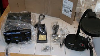
Picture of everything as I was unpacking it. One thing that isn't obvious is that on the nozzles, instead of getting four different ones, I got one "big" one, one "small" one and two of the "Second biggest ones".. the problem with this is the one I would probably use all the time would have been the "second smallest one". I'm going to contact the seller and see if I can't get it sent to me. **SIGH**
When inspecting the unit.. the little Chinese "warranty seal" on the back was already broken. I also noticed that the four holes on the back of the unit had two nylon punch in seals on one side but not on the other! I decided I better investigate. I opened up the unit because it didn't look right and the seal was broken already anyway!
Here is what I discovered in my unit:
The control board on the back of the unit is mounted using "punch in" Nylon standoffs. The ones of the right back side (right as seen from the front) of the unit were sheared off. The part of the standoff that was sheared off was nowhere to be found in the box, meaning that either the factory in China packed it broken or it was repacked broken in Lincoln, NE by the e-bay seller. (I don't care which!) I couldn't let this board float since the little "fish tank" type pump in the unit is on rubber mounts.. too much vibration would cause this board to short against the case. I have to assume that since steel screws are not used.. nylon ones are.. unlike the board in the front of the unit... that it has to be isolated from the case at least with the 110V version). Here is a short video clip of the problem with the unit.
Yah, at that point I was getting pretty frustrated... but it worked out OK after I cobbled together a fix (and improvement) out of hardware I bought for the Amplifier project.
I think I'll get four nylon screws of the appropriate length and get rid of the "punch in" fit standoffs completely.
I did fire the thing up and both the iron and hot air gun work well. Extremely well.. so it overall is working out OK. I'm just disappointed I got the broken one (AGAIN).. it always happens to me. My whole frickin' life seems to be fixing other peoples screw-ups. Two out of two of my recent Chinese made purchases I had to rebuild a part of to get them to work as designed. We *might* have a chance in the US after all if this is the typical QC over there!
I have a PC board that I got a couple of years ago at the CSVHF Society Conference cheap for the purpose (it was sold that way) of getting a bunch of SMA connectors off of it. It was nearly impossible to do this before hot air. It's easy now. I will make a video tomorrow showing how easy it is to remove SMT IC's, chip parts and RF connectors with the hot air. It's getting too late tonight.
But because of the scratches on the case, the loose iron tips and broken bag to store them in... the wrong nozzle in the set of four and the broken standoffs on the unit.. I can at best give it another C-...
Fixed.. it's a B... Which I suppose isn't bad for $140 delivered. But if those guys in Nebraska really expect to eventually get $230 for it.. no way, no how...One word for them: Aoyue.
Last Weekend...
A quick off topic posting here in the midst of a blizzard...
The weekend I was unable to work on the projects because I was in Des Moines, IA to get my last adopted child (which is the youngest boy or the third oldest) a Certificate of Citizenship from the Department of Homeland Insecurity.
Even though a law was passed in 2000 effective 2/2001 that automatically gave foreign born children (<18 years old) citizenship upon adoption finalization by US parents, for some reason most of the federal government (but the State Department does recognize the law) still doesn't recognize this.. even the USCIS (former INS). So, for something "automatic" we still have to pay $450+ and go through the hoopla. It's a good thing that ten years later the government hasn't revisited the issue of the federal government not recognizing the federal government laws. But that's okay.. your health care is in good hands! (Trust me!) If it were the other way around it would be "fraud, waste and abuse", but that only applies on "what you can do for the country" and not "what the country can do for you."
Here is some pictures of the hoopla. The last one we went to was a small event in West Branch, IA at the Herbert Hoover museum. This time the Governor of Iowa, Terry Branstad, wished to attend and former governor Robert Ray also apparently wanted to attend so it was a big formal deal instead of a simpler and better organized smaller event like last time (100 miles closer to home too...)
But I suppose that was okay.. it worked out okay.. at least the Blizzard waited a couple of days.


Of course I'll do the obligatory clan picture:

But boy.. it's 100% better for rework than trying to use an iron.. even for through hole parts.
I'll try to put a post up that is informative and detailed. I'm snowed in probably until Thursday... so if I have power, I'll try to do some project work. So far, so good...knock on wood..
*I'll go over this all on the next post...
The weekend I was unable to work on the projects because I was in Des Moines, IA to get my last adopted child (which is the youngest boy or the third oldest) a Certificate of Citizenship from the Department of Homeland Insecurity.
Even though a law was passed in 2000 effective 2/2001 that automatically gave foreign born children (<18 years old) citizenship upon adoption finalization by US parents, for some reason most of the federal government (but the State Department does recognize the law) still doesn't recognize this.. even the USCIS (former INS). So, for something "automatic" we still have to pay $450+ and go through the hoopla. It's a good thing that ten years later the government hasn't revisited the issue of the federal government not recognizing the federal government laws. But that's okay.. your health care is in good hands! (Trust me!) If it were the other way around it would be "fraud, waste and abuse", but that only applies on "what you can do for the country" and not "what the country can do for you."
Here is some pictures of the hoopla. The last one we went to was a small event in West Branch, IA at the Herbert Hoover museum. This time the Governor of Iowa, Terry Branstad, wished to attend and former governor Robert Ray also apparently wanted to attend so it was a big formal deal instead of a simpler and better organized smaller event like last time (100 miles closer to home too...)
But I suppose that was okay.. it worked out okay.. at least the Blizzard waited a couple of days.

The Spinner kid clan w/Iowa Governor Terry Branstad on Sunday.

Youngest boy w/COC. The other three kids got theirs in West Branch three years ago.

On topic: I received the Hot Air Rework station today. Even though I like it, I had to repair it before I could use it. I hate to do it but I actually might leave a Neutral on e-bay as the shipping damage to the unit didn't happen on the Lincoln, NE to rural Linn County, IA trip because the pieces that sheared off weren't in the box from Lincoln, NE, which was in good shape. So even though it was obviously inspected*, it was shipped from the seller in an already damaged state.
But it still was very cheap (inexpensive.. but cheap still) and really I don't know how I lived w/o a hot air tool. You might want to spend a little more for a Aoyue though... I would if I had it to do again. There are about four minor things wrong with the unit I got... I'll detail that later on my next post. I still have some multimedia stuff to do for it. The soldering iron with it is actually pretty decent too. It does work fine since I fixed it.
But boy.. it's 100% better for rework than trying to use an iron.. even for through hole parts.
I'll try to put a post up that is informative and detailed. I'm snowed in probably until Thursday... so if I have power, I'll try to do some project work. So far, so good...knock on wood..
*I'll go over this all on the next post...
Subscribe to:
Posts (Atom)